Cateye Ergociser Series 1000 Service Manual
28
EC-1200 EC-1600 EC-3600 EC-3700
Applicable Models:
I
mA
I
mA
ON
OFF
ES-4
Perform the positional correction of the core slit section after
detaching the frame cover and turning off the power. (See the
Sections D-1 & D-2 "Removing the Frame Covers.")
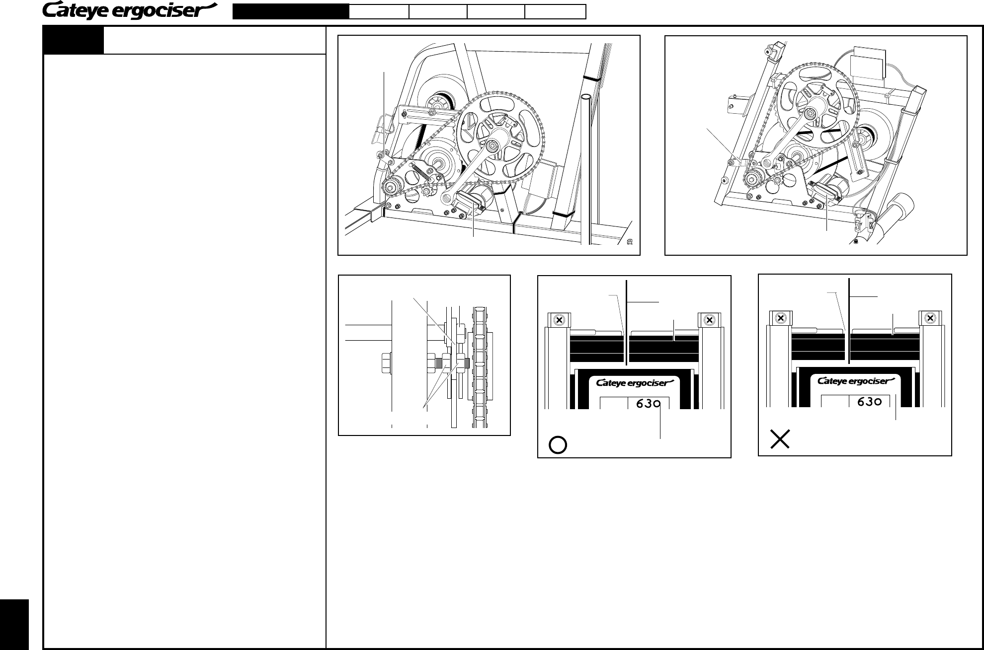
[1] Correction with Nuts of Workload Unit Reinforcing Metal Base
This correction is a minor correction method which allows
adjustment by the fastening force of the frame-side nuts of the
workload unit reinforcing metal base.
1. Check the contacting area by slowly rotating the copper disk
plate with your hands.
2. Adjust the two frame-side nuts of the workload unit reinforcing
metal base in the following procedures. (Fig. 1)
A.Loosen the nut on the workload unit side, and the nut on the
frame side (Fig. 1).
B.If the right side of the copper disk plate contacts the core,
when the main unit is viewed from the direction as depicted
in Fig. 3, fasten the frame-side nut.
C.Then, fasten the frame-side nut on the other side until the
copper disk plate comes close to the center of the core slit
(Fig. 2). [ Rotate the copper disk plate slowly, and check for
any contacts on the entire area of the plate.
D.Fasten the nuts which had been tightened in the above step
A.
[2] In case correction is not possible by the method stated in [1].
Replace the whole workload unit. (See the Section MS-2 "Replacing
the Workload Unit (w/ Flywheel).")
ES-4
Correcting the Position of Solenoid Coil
Workload Unit
Reinforcing Metal
Base
Solenoid Coil
EC-1200 & EC-1600
Workload Unit
Reinforcing
Metal Base
Solenoid Coil
EC-3600 & EC-3700
Fig. 1
Workload-Unit-
Side Nut
Frame-Side Nut
Fig. 2
Core Slit
Copper Disk Plate
Core
Correct Position
Solenoid Coil
Fig. 3
Core Slit
Copper Disk Plate
Core
Copper disk plate contacts the core.
Solenoid Coil
Correcting the Position of Solenoid Coil
Workload Unit Reinforcing
Metal Base


