


Cateye Ergociser Series 1000 Service Manual
24
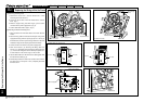
EC-1200 EC-1600 EC-3600 EC-3700
Applicable Models:
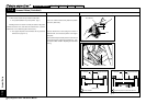
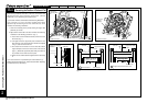
Cable Holders
ON
OFF
ON
OFF
ES-1
ES-1
Inlet Metal Base
Fig. 1
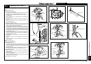
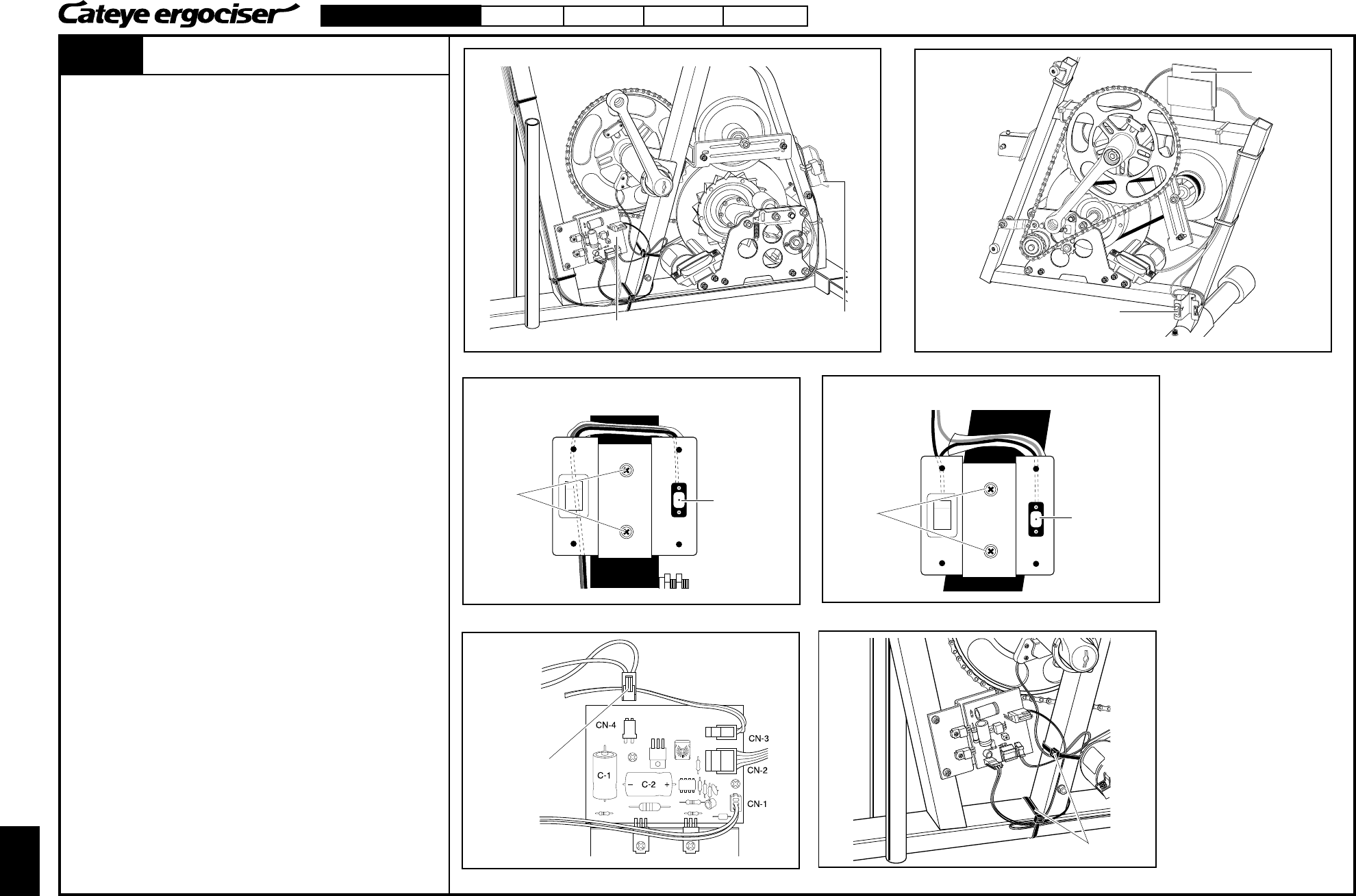
[A] Removing the Wiring Parts
1. Remove the frame cover. (See the Sections D-1 & D-2
"Removing the Frame Covers.")
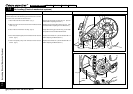
2. Loosen the two screws on the inlet metal base to remove
them. (Fig. 1)
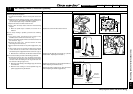
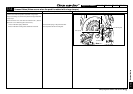
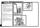
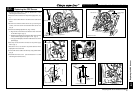
3. With the stopper being held with fingers, pull the CN-4
connector off the power supply board. (Fig. 2)
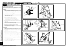
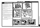
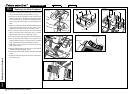
4. Cut the cable holder with a nipper. (Fig. 3)
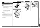
[B] Mounting the Brand New Wiring Parts
1. Mount the brand new inlet metal base to the frame with two
screws.
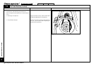
2. Pass the wiring cable from beneath the DC jack of the power
supply board along with the square pipe (21mm x 21mm) to
the left direction, and then pass it through the back of the inlet
metal base along with the square pipe toward the switch.
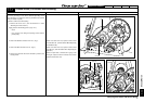
3. Connect the CN-4 connector to the power supply board.
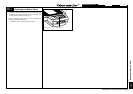
4. Refer to the Section (2) "Checking the Wiring within the
Frame" of T-1 "No Display on the Control Unit after Power ON"
(1) , measure the voltage across the electrolytic capacitor C-1
to check that it is in the correct range of 14V and 19V.
5. Use the cable holder to fix the CDC sensor cable together with
the solenoid coil cable. (Fig. 3)
6. Provisionally connect the control unit, and check the unit works
fine after turning on the power. Then, completely assemble
the frame cover.
Screws
ON
OFF
Replacing the Wiring within the Frame
EC-1200 & EC-1600
EC-3600 & EC-3700
Inlet Metal Base
Power Supply Board
Power Supply
Board
Inlet Metal Base (for Upright Type)
DC Jack
Inlet Metal Base (for Recumbent Type)
Screws
DC Jack
Fig. 3
Fig. 2
Power Supply Board
Hold the stopper.
Replacing the Wiring within the Frame