


Cateye Ergociser Series 1000 Service Manual
36
EC-1200 EC-1600 EC-3600 EC-3700
Applicable Models:
MS-1
MS-1
Derailleur
Spring
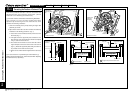
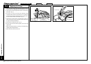
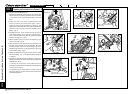
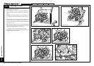
Replacing the Workload Unit (w/o Flywheel) (2)
Mounting the Brandnew Workload Unit
1. Assemble the brandnew workload unit so that it will engage
with the workload unit mounting metal base of the frame (Fig.
1). Be careful that the copper disk plate will not touch the
frame.
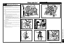
2. Tighten the crank nut by using a cotterless gear crank
removing/ fastening tool and a wrench (Figs. 2 and 3).
Tightening torque should be 350kg cm to 400kg·cm, and
tighten the nut until the end of the crank shaft can level with the
end surface of the nut. Then, put the crank cap with a coin or
the like. (Fig. 4)
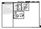
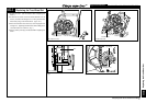
3. Assemble the chain. Chain should first be set on the free
wheel before setting it to the upper part of the large gear.
Then, a forward rotation of the crank will enable the complete
setting on the large gear. (Fig. 5)
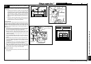
4. Set the derailleur spring to the pawl of the derailleur to give
tension to the chain. (Fig. 6)
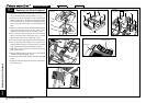
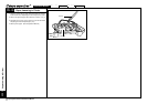
5. Adjust the position of the workload unit so that the tension of
the chain at the workload unit can be adequate. Move the
workload unit back and forth so that the longer edge of the
derailleur fixing metal base can be positioned at a right angle
to the derailleur spring. (Fig. 6)
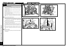
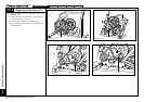
6. Tighten the workload unit fixing screw (two screws on either
right and left sides). (Fig. 7) The tightening torque is 90kg·cm
to 120kg·cm.
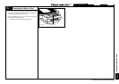
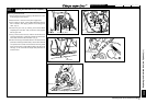
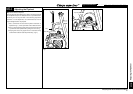
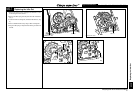
7. Assemble the workload reinforcing metal base in between the
bolts at the workload side and the frame side, and tighten the
bolts with nuts. (Fig. 8)
* In case the nut is screwed in at the position where the
workload-unit-side workload unit metal base is supposed to be
mounted, remove the nut.
* The tightening torque at the workload unit side should be
90kg·cm to 120kg·cm, and the nut at the frame side should be
provisionally tightened.
Fig. 2
Workload Unit Fixing Metal Base
Fig. 1
Workload Unit
Wrench
Cotterless Gear Crank
Removing/Fastening Tool
Fig. 3
Wrench
Cotterless Gear Crank Removing/
Fastening Tool
Fig. 4
Coin
Crank Cap
Fig. 5
Chain
Upper Part of Large Gear
Fig. 6
Derailleur
Fig. 7
Workload Unit Fixing Screw
Fig. 8
Workload Unit Reinforcing Metal
Base
Frame-Side Bolt
Workload-Unit-
Side Bolt
Replacing the Workload Unit (w/o Flywheel) (2)