3 - 20
INSP
ADJ
VALVE CLEARANCE INSPECTION AND ADJUSTMENT
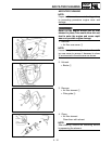
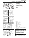
3. Remove:
• Right radiator
Refer to “RADIATOR” section in the
CHAPTER 4.
• Carburetor
Refer to “CARBURETOR” section in the
CHAPTER 4.
• Spark plug
• Upper engine bracket
• Cylinder head cover
Refer to “CAMSHAFTS” section in the
CHAPTER 4.
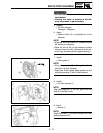
4. Remove:
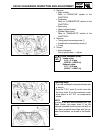
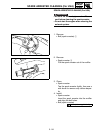
• Timing mark accessing screw 1
• Crankshaft end accessing screw 2
• O-ring
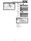
5. Check:
• Valve clearance
Out of specification → Adjust.
Valve clearance (cold):
Intake valve:
0.10 ~ 0.15 mm
(0.0039 ~ 0.0059 in)
Exhaust valve:
0.17 ~ 0.22 mm
(0.0067 ~ 0.0087 in)
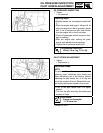
Checking steps:
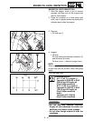
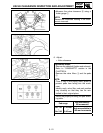
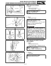
• Turn the crankshaft counterclockwise with
a wrench.
• Align the T.D.C. mark a on the rotor with
the align mark b on the crankcase cover
when piston is at T.D.C. on compression
stroke.
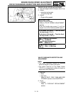
N
OTE:
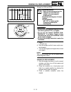
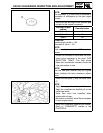
In order to be sure that the piston is at Top
Dead Center, the punch mark c on the
exhaust camshaft and the punch mark d on
the intake camshaft must align with the cyl-
inder head surface, as shown in the illustra-
tion.


