


2 - 24
SPEC
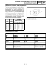
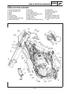
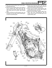
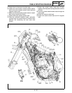
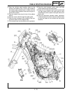
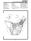
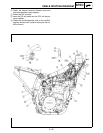
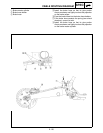
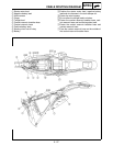
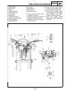
CABLE ROUTING DIAGRAM
1
Hot starter cable
2
Cable guide
3
Throttle cable (return)
4
Throttle cable (pull)
5
Ignition coil
6
Coolant reservoir breather
hose
7
Rectifier/regulator
8
Coolant reservoir hose
9
Rectifier/regulator lead
0
Clamp
A
CDI unit lead
B
CDI unit
C
CDI unit band
D
CDI unit stay
E
Rectifier/regulator bracket
È
Pass the throttle cables and
hot starter cable through the
cable guides.
É
Pass the throttle cables and
hot starter cable between the
radiator and frame, then under
the radiator mounting boss.
Ê
Pass the throttle cables on the
outside of the ignition coil.
Ë
Pass the carburetor breather
hose (of the throttle cable
cover) through the hose holder.