


– +
ELEC
6 - 2
MAP-CONTROLLED CDI UNIT
MAP-CONTROLLED CDI UNIT
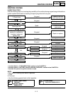
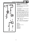
A map-controlled, CDI ignition system is used in the WR250F.
The microcomputer in the CDI unit detects the engine speed and throttle position, thus determining
the optimum ignition timing through the entire operating range. In this way, quick throttle response
can be achieved according to various riding conditions.
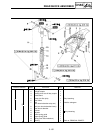
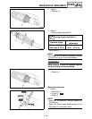
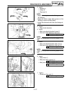
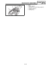
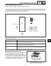
CDI unit
Throttle position sensor
Pickup coil AC magneto rotor
Ignition coil
■
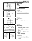
Function of Component
Component Function
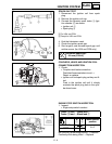
Throttle position sensor Detects throttle valve opening and inputs it into the computer in the
CDI unit as a throttle opening signal.
Pickup coil Detects signal rotor revolutions and inputs them into the computer in
the CDI unit as engine revolution signals.
CDI unit The signals of the throttle position sensor and pickup coil sensor are
analyzed by the computer in the CDI unit, which then adjusts ignition
timing for the operation requirements.
■
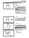
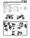
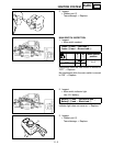
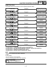
Principal of 3-Dimensional Control
Conventionally, ignition timing was controlled only
by engine revolutions (2-dimensional control).
However, ignition timing needs advancement also
by engine load. Thus, accurate ignition timing can
be determined by adding throttle opening to deter-
mine ignition timing (3-dimensional control).
3-D Image Map of Ignition Timing
(different from actual characteristics)
Revolutions
Ignition timing
Throttle opening
6