


6 - 22
– +
ELEC
THROTTLE POSITION SENSOR SYSTEM
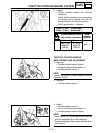
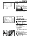
4. Adjust:
• Engine idling speed
Refer to “ENGINE IDLING SPEED
ADJUSTMENT” section in the CHAPTER
3.
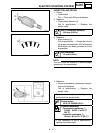
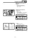
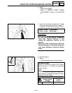
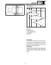
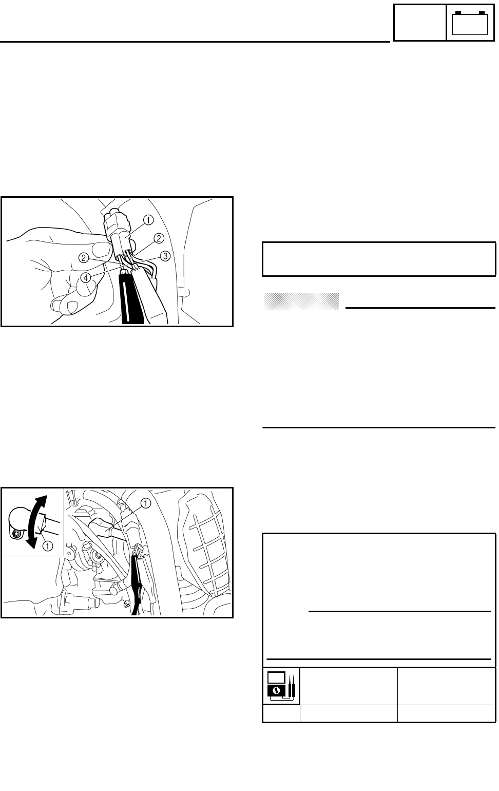
5. Insert the thin electric conductors 2 (lead)
into the throttle position sensor coupler 1,
as shown, and connect the tester to them.
CAUTION:
• Do not insert the electric conductors
more than required because it may
reduce the waterproof function of the
coupler.
• Make sure that a short-circuit does not
develop between the terminals because it
may cause damage to electrical compo-
nents.
Tester (+) lead
→
Yellow lead
3
Tester (–) lead
→
Black lead
4
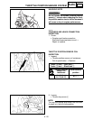
6. Start the engine.
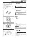
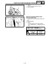
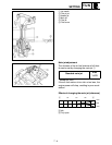
7. Adjust:
• Throttle position sensor output voltage
Adjustment steps:
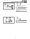
Adjust the installation angle of the throttle
position sensor 1 to obtain the specified
output voltage.
N
OTE:
Measure the output voltage accurately with a
digital electronic voltmeter that gives an easy
reading of a small voltage.
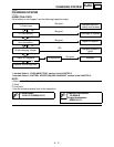
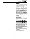
Throttle position
sensor output
voltage
Tester selector
position
0.58 ~ 0.78 V DCV