


M851 WristApp Design Guide Rev 1.2
Timex Corporation 64
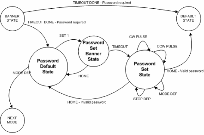
4.20 Setting
The kernel provides macros that will change the events generated by the CW and CCW switches. During
power-up, the reset handler will read the bond options to determine the type of setting mechanism that the
watch will use. These are the crown-set and ring-set mechanism.
Mechanical Overview:
An upward movement of the crown will trigger the CW pin and a downward movement will
trigger the CCW pin. In the ring mechanism, a rightward movement will trigger the CW pin and a
leftward movement will trigger the CCW pin.
To simplify the conventions used for directions, only two directions are used: Clockwise and
Counter-Clockwise. So for a crown mechanism, a forward movement will be clockwise direction.
For the ring mechanism, a leftward movement will be the clockwise direction.
The hardware drivers then provide a software abstraction layer that simplifies the applications
interaction with the CW and CCW switches by consistently dealing with CW and CCW direction.
The kernel provides two general types of events triggered by the CW and CCW switches – Edges and
Pulses. Edge events are generated with each transition of the signals. The pulse events are generated from
the number of pulses (a high-low-high transition) detected within a sample window of 125ms. No pulse
events are passed if no pulses are detected. By default, the switches will generate edge type events.
4.20.1 CW/CCW Event Swapping
The kernel provides a macro to swap the CW and CCW events and to restore to default settings. This
allows the application to reverse the signals in the hardware driver level while still dealing with clockwise
and counterclockwise directions.
The swap operation is intended to have the application work with clockwise and counterclockwise
directions when selecting data.