


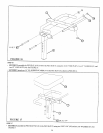
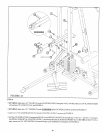
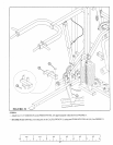
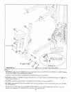
FIGURE 27
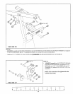
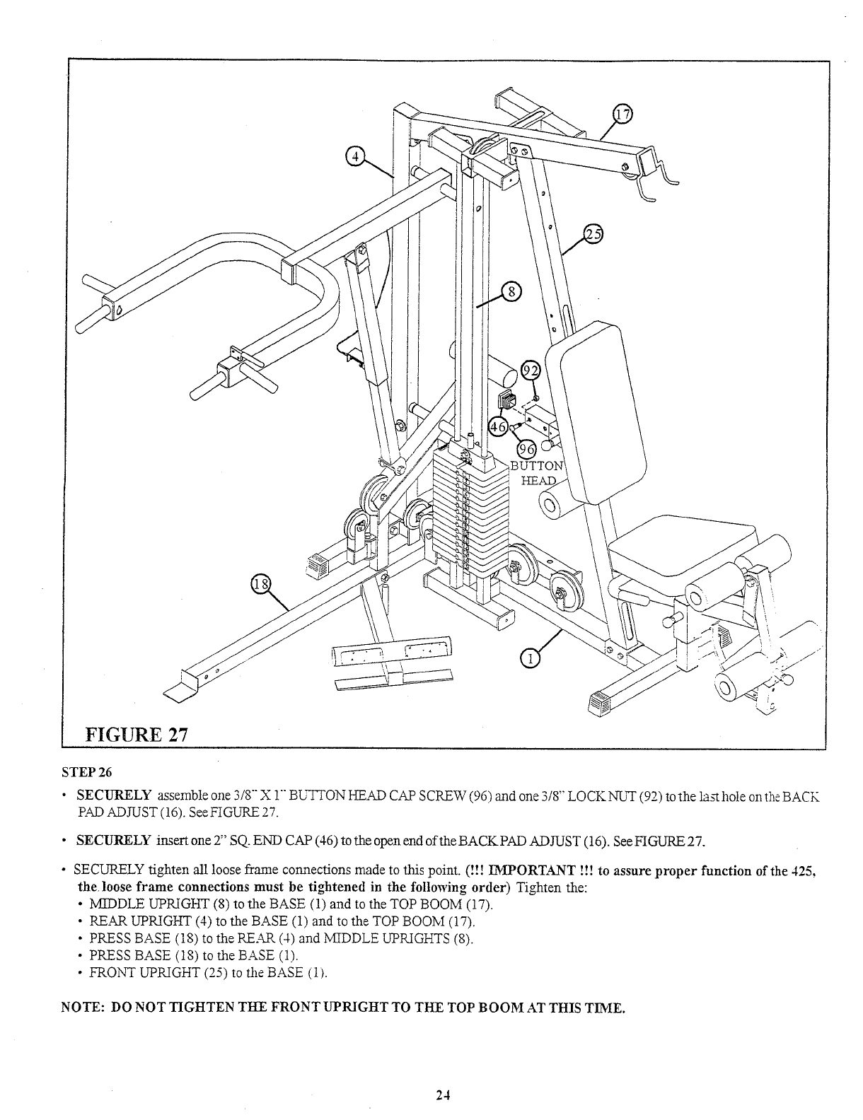
STEP 26
¯
SECURELY assemble one 3/8 X 1 BUTTON HEAD CAP SCREW (96) and one 3/8" LOCK_NUT (92) to the la~ hole on the
R~D ADJUST (16). See FIGURE 27.
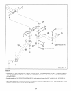
¯ SECURELY insert one 2" SQ, END CAP (46) to the open end of the BACK PAD ADJUST (16). See FIGURE
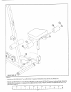
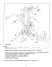
¯ SECURELY tighten all loose frame connections made to this poim. (!!! IMPORTANT !!! to assure proper function of the 425,
the. loose frame connections must be tightened in the following order) Tighten the:
¯ MIDDLE UPRIGHT (8) to the BASE (1) and to the TOP BOOM (17).
¯ REAR UPRIGHT (4) to the BASE (1) and to the TOP BOOM (17).
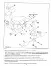
¯ PRESS BASE (18) to the RE.~ (4) and MIDDLE UPRIGHTS
¯ PRESS BASE (18) to the BASE (1).
¯
FRONT UPRIGHT (25) to the BASE (1).
NOTE: DO NOT TIGHTEN TIdE FRONT UPRIGHT TO THE TOP BOOM AT THIS TIME.
24