


Chapter 4. White-box thinking: Understanding collaboration 71
Note that logical elements can be either system elements that contain some
combination of hardware, software, people and information, or can be workers.
A worker is a human that is part of the system at the level above, and thus is not
represented as an actor. For example, if my enterprise (level 0) system is an
aircraft, we would likely consider the pilot to be inside the system of the aircraft,
thus the pilot does not appear as an actor at level 0—in fact, the pilot does not
appear at all at level 0. At level 1 we have the pilot, along with logical elements
such as navigation, weapons, environment, and so forth.
So the pilot could come out as a worker—a
human system element. The pilot is
still inside the enterprise, so we do not call him or her an actor, but within the
scope of level 1, all the system elements—system and worker—interact with
each other and are in a sense actors to each other. Note also that this is a
choice—the pilot could remain as a worker, hidden inside another system 1
element, say something like aircraft command and control. In this case, the pilot
would not appear at level 1, and could come out as a worker at level 2.
MDSD Step 10: Creating element context diagrams
As logical elements are determined, it helps to create context diagrams to show
these elements and their relationships to actors, and to each other. To create a
context diagram for a level 1 system element, we draw the element, along with all
of other elements with which it interacts. The elements can be one of three
possible types:
Actors, which also appear on the level 0 context diagram
Other level 1 system elements
Level 1 workers
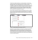
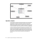
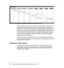
Context diagrams can be created for each logical element. Like an enterprise
context diagram, these show a certain element, its actors, and their I/O entities.
When drawn in a UML or SysML modeling tool, these context diagrams also
serve as collecting points for the operations that will be derived for these
elements (Figure 4-1). Note the shifting focus or context here—if we choose to
look at each element in a particular level as our system under consideration, the
other elements at that same level will be its actors.
2
With an initial cut at the logical elements for this model level or level of
decomposition, we are ready to proceed to the realization of the operations.
2
Currently no modeling tool handles this issue well. Several workarounds are possible—differing
coloration of the elements in different diagrams is a possibility.