


Chapter 7. MDSD and SysML 155
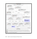
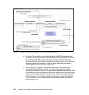
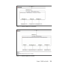
The Processing Unit communicates with the RainSensor using a flow port.
The data exchanged is two bitstreams, one containing the measurements
from the sensor and another containing synchronization data. The port is
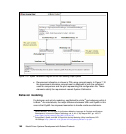
typed with a specification of these flows using the element
SensorECUCommunication (see Figure 7-6). Notice the direction of the flows in
the definition.
For convenience a flow port can be conjugated in the sense that its input and
outputs are inversed (flows declared as
in becomes out and vice-versa) with
respect to the definition of the interface. This is useful when connecting two
systems whose flow ports are conjugated with respect to each other. This is
the case for instance between the Processing Unit and the RainSensor in
Figure 7-5. A conjugated flow port is represented in black. Because the
synchronization data flow is declared as
inout, the conjugation of the port has
no effect on it.
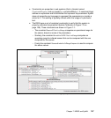
Note that in Figure 7-5 connectors between ports link parts defined within the
block. SysML actually allows direct connection between ports defined at
different levels of granularity, for example between a port and another one
defined
inside a part. This type of connector are called nested connectors. We
refer readers to the standard specification [OMG SysML] for more details
about these connectors.
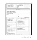
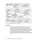
Flow ports are also useful to define physical contact between parts: For
example the Sensor Attachement unit is fixed to the Windshield using an
adhesive. The block representing the adhesive material AttachementAdhesive
(Figure 7-6) is used to type the flow port connecting these parts.
The addition of flow ports to SysML allows us to reason more effectively about
physical or electrical design issues. UML does not do this without inventing a
stereotype or extension which would provide the equivalent semantics.