


Chapter 5. Understanding distribution of responsibility 89
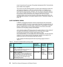
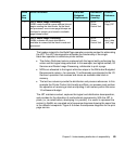
The header material for the Build Page operation provides context for elaborating
the JRT. This JRT decomposition allocates the functionality of the single
black-box operation to white-box printer entities:
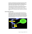
The Action Performed column captures both the logical entity performing the
action and the logical step performed. In this example, two logical entities, I/O
Services and Raster Image Processing, collaborate to print a page.
NFRs are allocated to the logical white-box steps in the White-box Budgeted
Requirements column—for example, 10 milliseconds are allocated to the I/O
Services’ operation that receives and stores an available data block in
memory.
The last two columns provide the distribution and process references. In this
example the Printer Control Unit locality and Data_rec process must perform
the operation of receiving a block and putting it into memory within the same
10 millisecond budget.
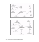
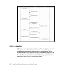
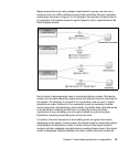
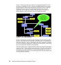
The JRT maintains context, captures the logical and distribution decomposition,
and provides for the allocation of nonfunctional requirements. With the JRT in
place, (or, as noted before, developing it in parallel), it is useful to represent the
content in SysML as a coupled set of sequence diagrams showing the same flow
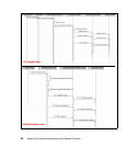
in the different viewpoints. Figure 5-5 shows the sequence diagrams for the print
page service.
3 LRF3: Raster Image Processing
WSB3: reads the buffer queue address list and
begins reading the data blocks. As the block
are processed, one or more page bitmaps are
rendered to memory and stored in available
page bitmap buffers.
DRF3:
Printer
Control Unit
PRF3:
Page_RIP
4 LRF4: Raster Image Processing
WSB4: indicates the input data block is
available for reuse after the block is read and
processed.
DRF4:
Printer
Control Unit
PRF4:
Input_data
_buff_mgt
White
-box
Step
Action Performed White-box
Budgeted
Requirements
Distribution
Reference
(Locality)
Process
Reference