


88 Model Driven Systems Development with Rational Products
more is learned over the course of the system development effort. Eventually the
entire model comes together.
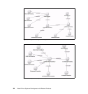
This is also true when deciding whether to reason about distribution issues first
with sequence diagrams, or with joint realization tables. In all likelihood, we
should perform both activities in parallel—we can use joint realization tables to
get a view of multiple dimensions, and we can use sequence diagrams to focus
on and reason about functionality in the viewpoint. We now turn to joint
realization tables, which we have actually used before and partially filled in, as
we did operation analysis in the logical viewpoint (refer to “Operation analysis” on
page 72).
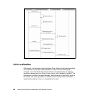
Joint realization tables
In MDSD, we distinguish between functional requirements and nonfunctional
requirements (NFRs). Functional requirements describe the system behavior as
well as the collaboration among system components to accomplish the system
behavior. NFRs pertain to how a system performs its functions and include
concerns such as quality, quantity, and timeliness.
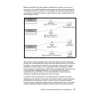
Joint realization tables (JRTs) decompose the system behavior in the context of
the logical and distribution architectures and, at the same time, assign
nonfunctional requirements to these system behavior steps
(services/operations). In a real sense, this is the missing link—the item that was
needed to connect object-oriented development models to the needs of the
engineering community developing large-scale systems.
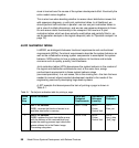
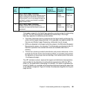
A JRT example that decomposes the task of printing a page is shown in
Table 5-1.
Table 5-1 Partial joint realization table for printing a page
White
-box
Step
Action Performed White-box
Budgeted
Requirements
Distribution
Reference
(Locality)
Process
Reference
1 LRF1: I/O Services
WSB1: receives the block and stores in an
available data buffer in memory.
SUP1: 10 ms DRF1:
Printer
Control Unit
PRF1:
Data_rec
2 LRF2: I/O Services
WSB2: updates the input data buffer queue
with the address of the received block and
sends the awaiting process input data buffer
queue address list to the Raster Image
Processing subsystem.
SUP2: 2 ms DRF2:
Printer
Control Unit
PRF2:
Input_data
_buff_mgt