


Chapter 5. Understanding distribution of responsibility 85
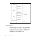
Sequence diagrams with localities
After drawing a locality view, the next step is to analyze how the operations on
the various logical elements will be deployed at these places. To do this we
construct a new sequence diagram, similar to the ones we have already done,
but instead of the logical elements and actors, we use the localities and the
actors as the lifelines. We create such a locality interaction (sequence) diagram
for each operation at the level above which we are doing our locality analysis.
Thus there will be a locality interaction diagram for each white-box sequence
diagram at this level.
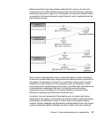
To determine the messages between the elements on our locality interaction
diagram, we simply copy the messages from the white-box sequence diagram
one-for-one onto the new diagram. The messages are the same; the difference is
the elements to which the messages go:
In the white-box sequence diagrams, messages are requests of some logical
system element to perform some operation.
In the locality interaction diagram, the same messages indicate where the
operation is to be implemented.
We can think of it as a request being made of a distribution location, where part
of the system is implemented. Notice that it is quite common to have numerous
reflexive messages (messages that go from an element back to itself), because
this means that a number of operations happen consecutively at one place.
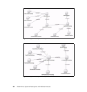
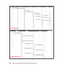
Figure 5-3 shows how the initiate new sale operation from an earlier illustration is
distributed across the locations in the retail system.