


Chapter 6. Tool support for MDSD 95
On balance, we find that flip charts are often the best way to begin a modeling
effort and to do the initial drafting of model elements, use case flows, and
diagrams. When the model has reached some level of stability, we find it best to
put the model into a UML or SysML modeling tool, such as Rational Software
Modeler, Rational System Developer, or similar, and maintain it there.
In other situations, where the engineers involved are experienced in using
modeling languages and modeling tools, it might be better to proceed directly to
using the modeling tool to capture the modeling work right from the start.
Organizing an MDSD model using tree-structured packages in a modeling tool
can be confusing. The following sections detail an approach that we have found
to work.
Level 0 model organization
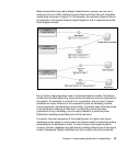
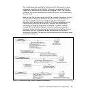
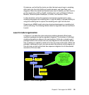
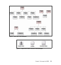
In Figure 6-1 we show the main enterprise modeling elements. Blue boxes
represent packages and yellow represent diagrams. The locations of individual
modeling elements are shown in the next sections. At the top, a single Level 0
package contains the context and use case diagrams for the enterprise. Below
that, a package is created to contain all of the use cases at this level. Within this
package, a package for each use case contains the optional activity diagram for
this use case, as well as the black box sequence diagrams for all documented
scenarios of this use case.
Figure 6-1 Level 0 model organization
Project
Level 0
Use Cases
L0 Use Case “A”
L0 Use Case “B”
Activity Diagram
Sequence Diagram
(Black Box)
Context Diagram
Use Case
Diagram
At Level 0, only use
cases appear in the
model; Level 0
operations will
appear in their
realization in Level 1.