


138 Model Driven Systems Development with Rational Products
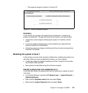
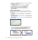
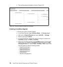
The resulting sequence diagram is shown in Figure 6-58.
Figure 6-58 White-box sequence diagram with messages
Creating a localities diagram
In this task you create a localities diagram:
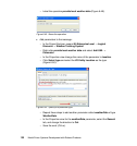
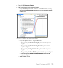
In the Project Explorer, expand Systems Model → 01 System Level.
Right-click on Physical Elements and select Add UML → Package.
Name the package Localities.
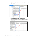
In the Project Explorer, change the name of the diagram created in the
Localities package from Main to Localities.
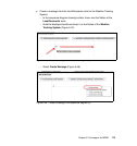
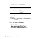
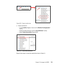
Hover over the drawing surface of the Localities diagram (it should have
opened when you created the Localities package) and select the Add
stereotyped class icon. Select Create <<locality>> Class (Figure 6-59).
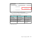
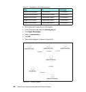
Use this method to create the following classes:
– DopplerControlCenter1
– DopplerRadarStation1
– DopplerRadarStation2
– DopplerRadarStation3
– GroundStation1
– WeatherTrackingSystem1