


Chapter 6. Tool support for MDSD 109
Creating MDSD artifacts
Creating artifacts to capture the essence of the MDSD process involves a small
number of diagrams. We include here instructions on how to draw them using
IBM Rational Systems Developer.
2
UML diagrams for systems modeling
There are only a few diagrams needed in UML to capture the essence of the
MDSD process. The following sections assume that you have a Rational
modeling tool and the MDSD profile. We guide you through the following tasks:
Load the MDSD profile.
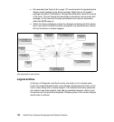
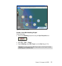
Draw a context diagram.
Draw two sequence diagrams for flowdown.
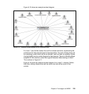
Draw a Locality diagram.
Preparing the environment
IBM Rational Systems Developer is an Eclipse-based integration, design, and
construction product that enables systems and software architects and
developers to create applications that are optimized for C++ and Java™ SE.
Rational Systems Developer also provides modeling capabilities supporting UML
2.0.
Rational Systems Developer is based on the Eclipse Workbench. If you are not
already familiar with the Eclipse Workbench environment, take some time during
this section to explore the environment.
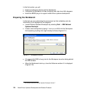
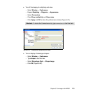
You will configure the environment in preparation for this section. You will
customize the way that UML connectors are displayed on diagrams to make the
diagrams more readable. We do not have to see the multiplicity and roles
information for this purpose, so we configure the environment so that they are not
shown in the diagrams.
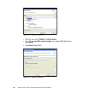
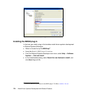
Because Rational Systems Developer is based on Eclipse, we have the ability to
create and use plug-ins to provide additional features and functionality. In this
section you are installing a plug-in that provides additional tools to support and
enable model-driven systems development. When you install this plug-in, take
some time to see what the effect was and consider how it can be a valuable
capability to have.
2
They can also be created using Rational Software Architect or Rational Software Modeler.