


154 Model Driven Systems Development with Rational Products
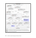
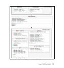
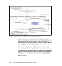
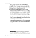
Figure 7-5 SysML Internal Block Diagram of the Rain Sensing Wiper system
In Figure 7-5 we refine our initial description of the RSW by showing how
parts are interacting inside the block named Rain Sensing Wiper. Previously
to constructing the IBD, we have to define a model for the associations
characterizing the relationships between the different blocks. Also, additional
blocks are defined for example to type the ports. We show this model in
another BDD that can be found in Figure 7-6.
The central part of Figure 7-5 consists of the parts of the system that
represent the embedded hardware. The parts underneath are used for
mounting the system in the car. The parts above represent the software. A set
of standard ports and interfaces are defined to represent the functional aspect
of the communication between the parts. For example, the Processing Unit
(ECU) accesses the Actuation (interface) of the wiper through the interface
WiperECUCommunication. Details about the interfaces used in this IBD are
found in Figure 7-6.