


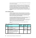

96 Model Driven Systems Development with Rational Products
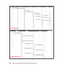
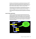
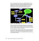
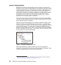
At level 1, the structure becomes a little more complicated (Figure 6-2). At the
top, there is a package for Level 1 and then immediately below that, any grand
context diagrams or grand use case diagrams created at this level. These two
diagrams show all or some of the level's logical elements and use cases,
respectively, and are optionally created if they add clarity to the model. If a
locality diagram is used at this level, it can be included here as well.
Figure 6-2 Level 1 model organization
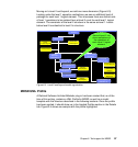
At level 1 and beyond, we create two sets of packages for the remaining model
elements. One holds the level 0 operation realizations, that is, the realization of
each level 0 operation. There is a package for each level 0 operation, containing
the white-box sequence diagrams for all scenarios of this operation. These items
serve to expresses the realization of this operation.
The other category (level 1 logical elements) contains a package for each logical
element at level 1. These elements were determined in the process of doing the
realizations of the level 0 operations. In each element package, you will see a
context diagram for this element, a corresponding optional use case diagram and
any joint realization diagrams.
Project
Level 1
Grand
Context Diagram
Grand Use
Case Diagram
Locality Diagram
Level 0
Operation
Realizations
L0 Operation “C”
Level 1 Logical
Elements
L1 Logical
Element “Z”
L1 Logical
Element “Y”
Context Diagram
Use Case
Diagram
Joint Realization
Diagram(s)
WB Exp
Seq Diagram
L0 Operation “D”
WB Exp
Seq Diagram
These are
operations of the
Level 0 logical
element, which is
the Enterprise