


Chapter 6. Tool support for MDSD 97
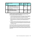
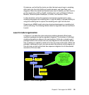
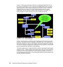
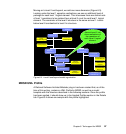
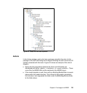
Moving on to level 2 and beyond, we add one more dimension (Figure 6-3).
Looking under the level 1 operation realizations, we see an additional level of
package for each level 1 logical element. This is because there are distinct sets
of level 1 operations to be realized here at level 2-n set for each level 1 logical
element. The remainder of the level 2 structure is the same as level 1. Levels
below level 2 are identical to level 2 in structure.
Figure 6-3 Level 2 and beyond model organization
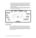
MDSD UML Profile
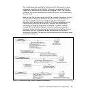
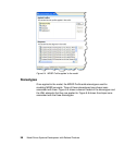
A Rational Software Architect/Modeler plug-in has been created that, as of the
time of this writing, contains a UML Profile for MDSD, as well as a model
template with the structure described in the following sections. Once the profile
has been applied, it should show up in the Applied Profiles section in the Details
tab. Figure 6-4 shows an example with the profile highlighted.
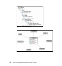
Project
Level 2..n
Grand
Context Diagram
Grand Use
Case Diagram
Locality Diagram
Level 1
Operation
Realizations
L1 Operation “E”
Level 2 Logical
Elements
L2 Logical
Element “P”
L2 Logical
Element “Q”
Context Diagram
Use Case
Diagram
Joint Realization
Diagram(s)
Level 1 Logical
Element “G”
Level 1 Logical
Element “H”
L1 Operation “F”
WB Exp
Seq Diagram
WB Exp
Seq Diagram
Here at Level 2, we
show realizations of
the operations of
each Level 1 logical
element.