


Chapter 6. Tool support for MDSD 133
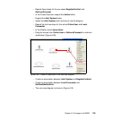
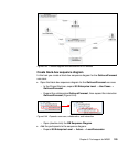
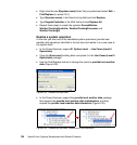
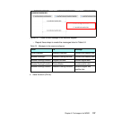
– The sequence diagram is shown in Figure 6-51.
Figure 6-51 Black-box sequence diagram
Summary
In this section you worked at the highest level of abstraction, modeling the
system as a black box. Through the course of this section, you have created:
A black-box context diagram identifying the system, I/O entities, and the
actors
A use case diagram identifying the various benefits (use cases) that the
system provides to its stakeholders
A black-box sequence diagram identifying the flow of events and operations
required of the system
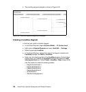
Modeling the system at level 1
In this section you work at the next level of abstraction, modeling the system as a
white box. When you have completed this section, you have created:
A white-box sequence diagram identifying the flow of events for the provide
local weather data operation.
New systems as identified during this white-box analysis.
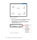
Identify systems that will collaborate at L1
In this task you identify the systems that have to collaborate to realize the level 1
use cases:
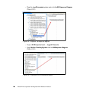
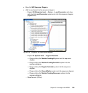
In the Project Explorer, expand the 01 System Level → Logical Elements →
${Building Blocks}.
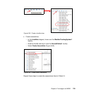
Right-click the ${system.name} folder and select Copy.
Right-click the Logical Elements folder and select Paste.