


G B
3
O W N E R ' S M A N U A L J 7 , J 7 F
S A F E T Y I N S T R U C T I O N S
This Owner’s Manual is an essential part of your
training equipment: reading all instructions in this
manual before you start using this appliance. The
following precautions must always be followed:
WARNING:
•
Never use extension cords between the treadmill
and your wall outlet. The device’s maximum power
consumption is 10 A (EU) / 20 A (US). Outlets
with uctuating voltage of more than 5 %, may
result in erratic performance or cause damage
to treadmill electronics. Using electrical power
other than that which has been specied in this
manual, will ultimately void any warranty, implied
or otherwise.
WARNING: to reduce any risk to persons:
•
Keep hands clear of any moving parts. Never
place hands, feet or any other objects into any
opening or under the treadmill.
•
Never leave the treadmill unattended when
plugged in. Unplug from outlet when not in
use, before putting on or taking off parts. To
disconnect, turn all controls to the off position,
then remove plug from outlet.
•
Close supervision is necessary when the
treadmill used by, on, or near children, invalids, or
disabled persons.
•
Use the treadmill only for its intended use as
described in this manual. Do not use attachments
not recommended by Tunturi.
•
Before you start using the treadmill, make sure
that it functions correctly in every way. Do not use
a faulty device.
•
Keep the cord away from heated surfaces.
•
J7 / J7F must not be used outdoors. J7 /
J7F tolerates an environment measuring +10°C to
+35°C. Air humidity must never exceed 90 %.
•
Do not attempt any servicing or adjustment
other than those described in this manual. The
given instructions must be followed carefully.
•
Never operate this treadmill if it has a damaged
cord or plug, if it has been dropped or damaged,
or dropped into water. Return the treadmill to a
service center for repair.
•
Never operate the appliance with the air
opening blocked. Keep the air openings free of lint,
hair, and the like.
•
Do not operate where aerosol (spray)
products are being used or where oxygen is being
administered.
•
Strong electromagnetic elds may cause
disturbances in the pulse / heart rate measurement.
•
The device must not be used by persons
weighing over 135 kg (300 lbs).
SAVE THESE INSTRUCTIONS!
WELCOME TO THE WORLD OF TUNTURI
EXERCISING!
Your choice shows that you really want to invest in
your well-being and condition; it also shows you
really value high quality and style. With Tunturi
Fitness Equipment, you’ve chosen a high-quality,
safe and motivating product as your training
partner. Whatever your goal in training, we are
certain this is the training equipment to get you
there.
A S S E M B LY
Before assembling the device, insure all parts are
present:
1. Frame
2. Power cord
3. Assembly kit (contents are marked
with an * in the spare part list)
In case of problems contact your Tunturi dealer.
The packaging includes a disposable silicate
bag for absorbing moisture during storage and
transportation. The directions left, right, front
and back are dened as seen from the exercising
position.
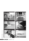
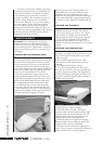
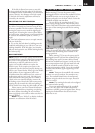
J7: HAND RAIL AND INTERFACE FIG 1,2,3
Turn the user interface until the holes for the
locking screws are in position and then attach by
tightening the 4 screws (M6x12) on the rear side.
Cut the green ribbon and attach the corner pieces
to the hand rail with Allen screws, do not tighten
much yet. Lift the handrail to the upright position,
place the cover tubes between corner pieces and
the frame and thread the attachment bolts through
the tubes. Tighten the bolts with nuts and the
Allen screws on both sides. Place the transportation
wheels on the axles on the lower end of the hand
rail, set the locking sleeve at the end of the axle
and attach it by knocking the assembly tool gently.
Attach the 2 screws (M6x12) on the front side of
the interface and remove the protective lm from
the display.
J7F: HAND RAIL AND INTERFACE FIG 4,5
Turn the user interface until the holes for the
locking screws are in position and then attach by
tightening the 4 screws (M6x12) on the rear side.
Cut the green ribbon of the hand rail. Push the
ends of the U-shaped frame of the front into
the hand rail ends and push the attachment bolts
into place. Run the elevation to 0 % (see Power
Cord, Tether Key and Interface) and lift the hand
rail to the upright position. Push the U-shaped
OW NER 'S MAN UAL • J7 • J 7F