


;TEP 9
~=r~.
PUSWPULL
CABL_ E
!
DO NOT OVERTIGHTEN!
/
/
SPRING PIN’--’
ASSEMBLY
DETAIL 9
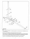
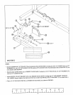
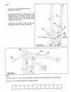
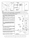
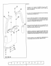
Assemble the PUSH/PULL CABLE from the PRESS ARM (8) to the SPRING PIN HOUSING and to the L-BRACKET on the
RECEIVING TUBE (13) as shown on FIGURE 9 and DETAIL 9 using the following steps:
¯
Thread the first 1/4-28 IN. NUT to the bottom of the threaded endof the CABLE. Allow the other 1/4-28 IN. NUT to hang loose
on the exposed CABLE until the SPRING PIN ASSEMBLY is attached.
¯ Securely assemble the SPRING PIN ASSEMBLY to the
SPRING PIN BARREL, (ll! IMPORTANT ![! TIGHTEN
THE NUT OF THE SPRING PIN ASSEMBLY SE-
CURELY)
¯ Swing the PRESS ARM (8) up until the SPRING PIN of the
PUSH/PULL CABLE engages in one of the adjustment
holes.
¯ Thread the second 1/4-28 IN. NUT onto the threaded end of
the CABLE, and cinch the two 1/4-28 IN. NUTS around the
flat.
¯ Use the ex-tra thread on the end of the CABLE to adjust out
slack. ( !!! DO NOT ADJUST OUT TO FAR !!! AL-
WAYS ALLOW SPRING PIN ASSEMBLY TO FULLY
ENGAGE)
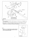
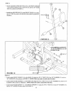
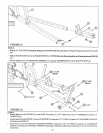
STEP 10
Securely tighten two 5/32" SET SCREWS (65) and inserl
two 3 X 2" END CAPS (75) into the open ends of PRESS
ARM (8) as sho~vn in FIGURE 10.
Securely tighten two 5/32" SET SCREWS (65) and inserl
two 2" SQ. END CAPS (76) into the open ends of PRESS
ARM LEVER (9) as shown in FIGURE 10.
Securely tighten one 3/8 X 1" BOLT (35), one 3/8" WASHER
(51), and one 3/8" LOCKNUT (48) to the bottom of
JUSTMENT SLIDE (6) as shown in FIGURE 10.
¯
Insert one 1-3/4" SQ. END CAP (77) into the end of AD-
JUSTMENT SLIDE (6) as shown in FIGURE 10.
FIGURE
[
1/2
I
1/2 ] 1/2
[
4 5 I
6
I I