


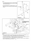
1/2" LOW
HEIGHT
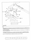
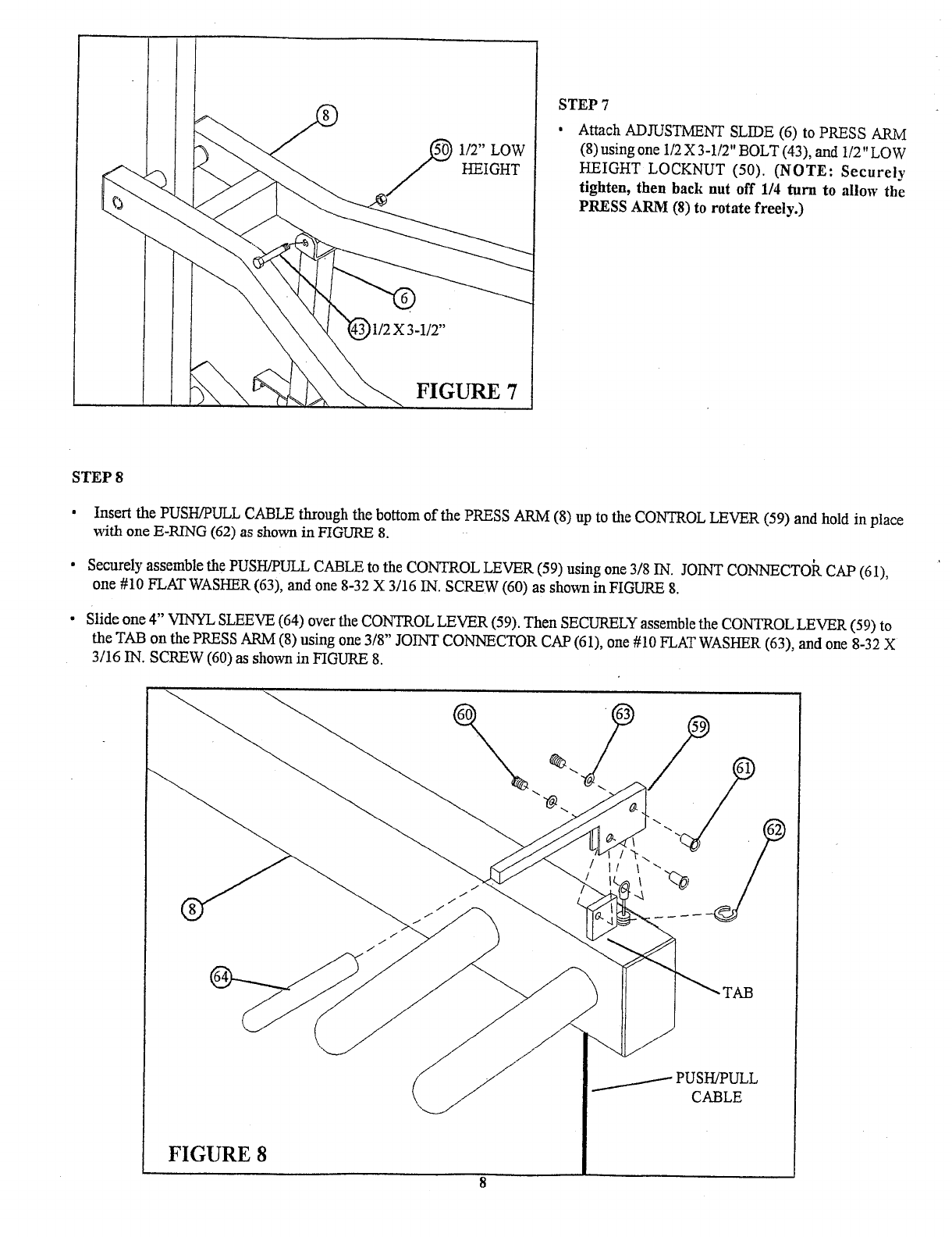
FIGURE 7
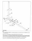
STEP 7
¯
Attach ADJUSTMENT SLIDE (6) to PRESS ARM
(8) using one 1/2 X 3-1/2" BOLT (43), and 1/2"
HEIGHT LOCKNUT (50). (NOTE: Securely
tighten, then back nut off 1/4 turn to allow th~
PRESS ARM (8) to rotate freely.)
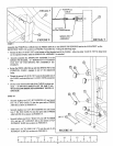
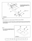
STEP 8
¯
Insert the PUSH/PULL CABLE through the bottom of the PRESS ARM (8) up to the CONTROL LEVER (59) and hold in place
with one E-RING (62) as shown in FIGURE
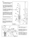
¯ Securely assemble the PUSH/PULL CABLE to the CONTROL LEVER (59) using one 3/8 IN. OINT CONNECTOR CAP (61),
one #10 FLAT WASHER (63), and one 8-32 X 3/16 IN. SCREW (60) as shown in FIGURE
Slide one 4" VINYL SLEEVE (64) over the CONTROL LEVER (59). Then SECURELY assemble the CONTROL LEVER (59)
the TAB on the PRESS ARM (8) using one 3/8" JOINT CONNECTOR CAP (61), one #10 FLAT WASHER (63), and one
3/16 IN. SCREW (60) as shown in FIGURE
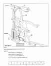
FIGURE 8