EPSON Stylus Pro 7000 Revision B
Disassembly & Assembly Disassembly Flow 133
4.2.3.5 Removing the Cutter Housing
1. Follow the instructions up to step 8 in “Removing the CR Board
Assembly” on page 132.
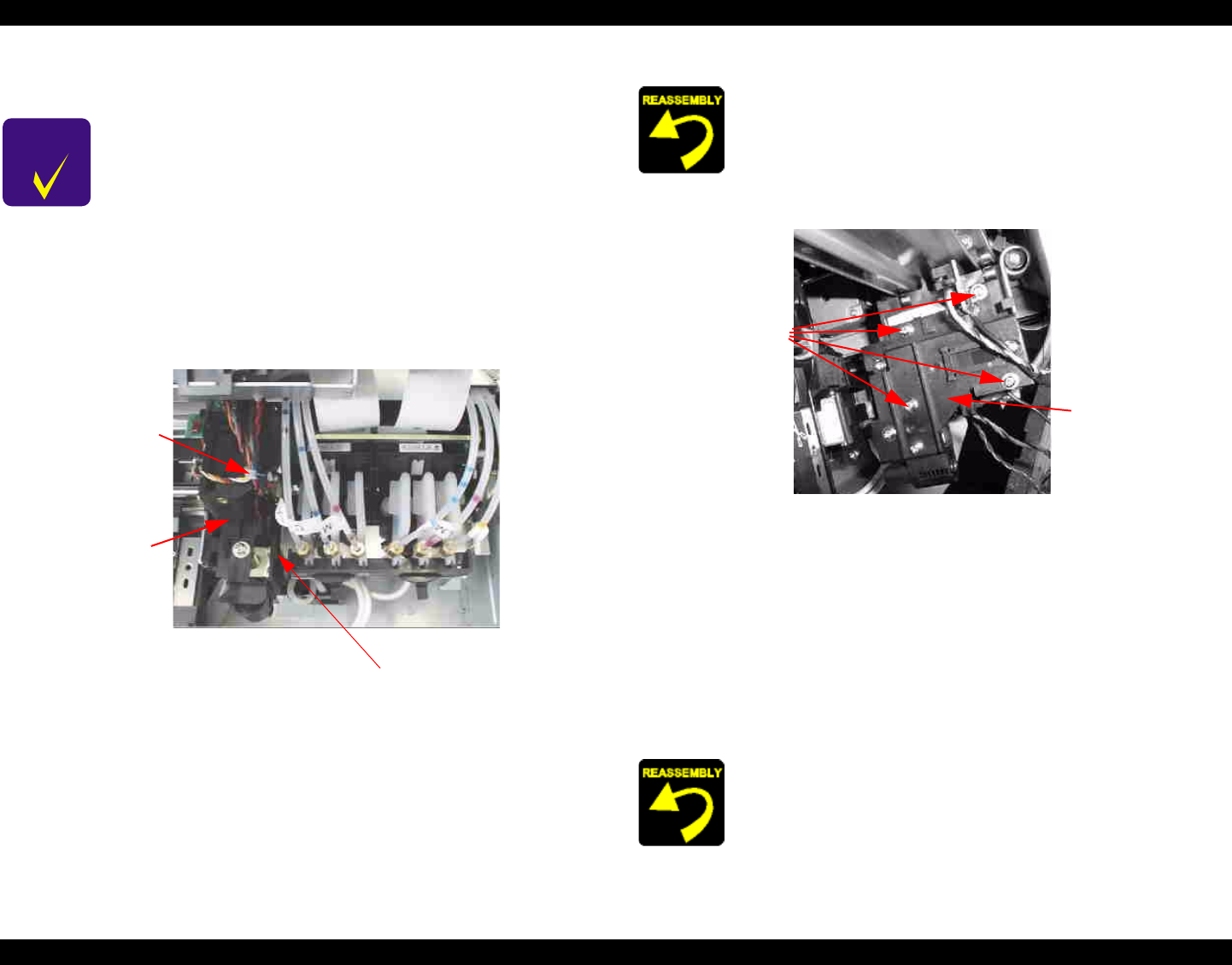
2. Cut the plastic band near the front of the cutter housing and pull the
sensor cables free.
Figure 4-41. Cutter Housing Removal 1/2
3. Remove the four screws (CP(W)M3x8) securing the cutter housing.
Figure 4-42. Cutter Housing Removal 2/2
4. Carefully, but forcefully, pull the cutter housing slightly to the left to
release it from the carriage, but do not pull the cutter housing completely
off. See Figure 4-41 and Figure 4-44 for photos of the T-shaped housing/
carriage lock mechanism.
5. Move the carriage slightly to the left so that there is nothing underneath
the P_EDGE sensor. Then carefully push the cutter housing in just a little
to make sure the sensor clears the carriage wall as you pull the cutter
housing to the left to remove it.
CHECK
POINT
Before each step in this operation, take a good look at the
relative parts and where they are or how they are housed.
This is not an easy procedure, and reassembly is even
harder if you do not pay strict attention to how the parts
fit together.
Read this entire section and become familiar with the
associated parts before starting.
Cut this
band
Cutter
housing
T-shaped
locking
mechanism
Remember to use a plastic tie band to secure the encoder
sensor, P_EDGE sensor, and ground cables in front of the
cutter housing. Otherwise, the cables may rub against and
interfere with the linear encoder.
Keep in mind that the P_EDGE sensor (and cable) goes on the
inside of the carriage frame but the rest of the cutter goes on
the outside. To wrap the sensor around the inside, push the
carriage back toward the HP until you find enough room to
make sure the sensor safely clears the carriage wall.
Four
screws
Cutter
housing
