


Service Manual Repair procedures 49
14. For Masimo models, continue with the next section. For Nellcor models, continue
with “Installing the SpO
2
board (Nellcor models)” on page 54.
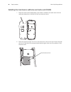
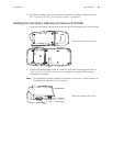
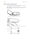
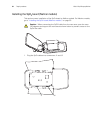
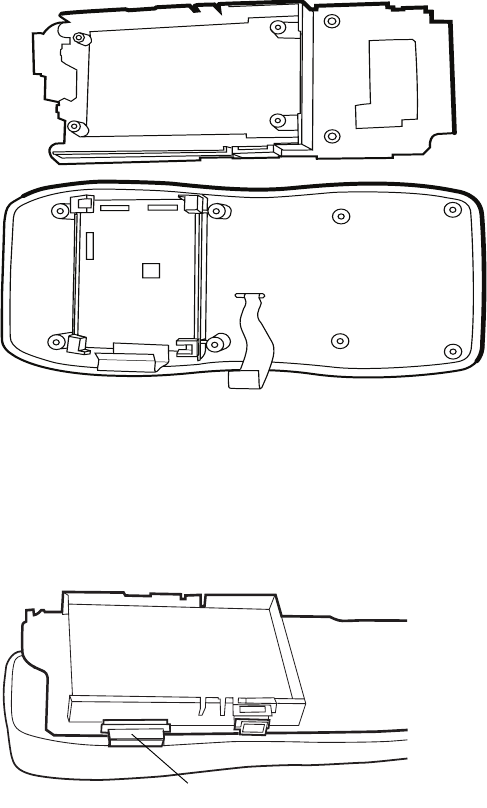
Installing the main board, subframe and radio card (2.4 GHz)
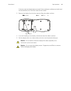
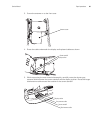
1. Install the main board, subframe and radio card as one assembly onto the front case.
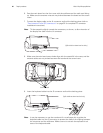
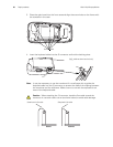
2. Connect the display cable to the J4 connector and lock the latching piece (refer to
“Zero Insertion Force (ZIF) connectors” on page 32 for complete ZIF connector
installation instructions.)
Note
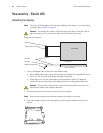
Tilt the assembly slightly toward the connectors, as shown, to allow insertion of
the display flex cable into the J4 connector.
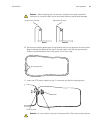
(SpO
2
shield not shown here for clarity.)
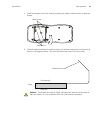
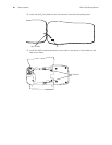
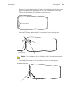
(SpO
2
shield not shown here for clarity.)
J4