11
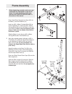
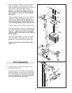
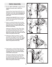
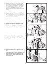
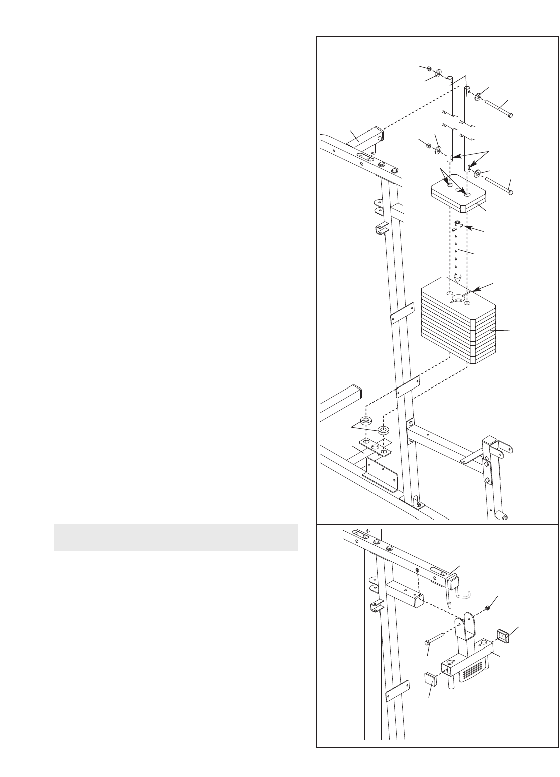
11. Insert two Weight Guides (17) into the indicated
holes in the Base (1). While a second person
holds the W
eight Guides, attach them to the Base
with an M10 x 155mm Bolt (66), two M10
W
ashers (77), and an M10 Nylon Locknut (80).
Make sure the slots in the Weight Guides are
on the bottom, as shown. Do not overtighten
the Locknut.
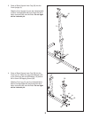
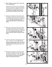
Slide two Weight Bumpers (51) onto the Weight
Guides (17). Slide six Weights (21) onto the
Weight Guides.
Make sure the Weights are ori-
ented with the deep pin grooves on the bot-
tom of the Weights and on the indicated side.
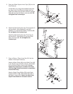
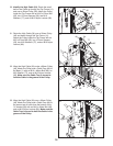
Insert the Weight Tube (23) into the Weights (21).
Lubricate the indicated holes in a Top Weight (22)
with grease. Slide the Top Weight onto the Weight
Guides (17).
Make sure the pin on the Weight
Tube (23) rests in the grooves in the bottom of
the Top Weight.
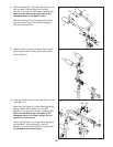
Attach the Weight Guides (17) to the Top Frame
(11) with an M10 x 155mm Bolt (66), two M10
Washers (77), and an M10 Nylon Locknut (80).
Tighten the M10 Nylon Locknuts (80) used in
steps 1–11.
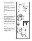
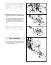
12.
Press two 50mm x 70mm Inner Caps (37) into
the Butterfly Frame (12).
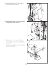
Lubricate an M10 x 77mm Bolt (75) with grease.
Attach the Butterfly Frame (12) to the
T
op Frame
(1
1) with the Bolt and an M10 Nylon Locknut (80).
Do not overtighten the Locknut; the Butterfly
Frame must be able to pivot easily
.
1
1
1
80
80
77
77
77
17
77
66
66
22
23
21
51
Lubricate
Slot
11
37
37
80
11
75
12
12
Arm Assembly
Pin
Groove
Pin


