


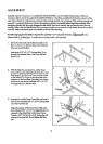
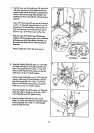
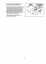

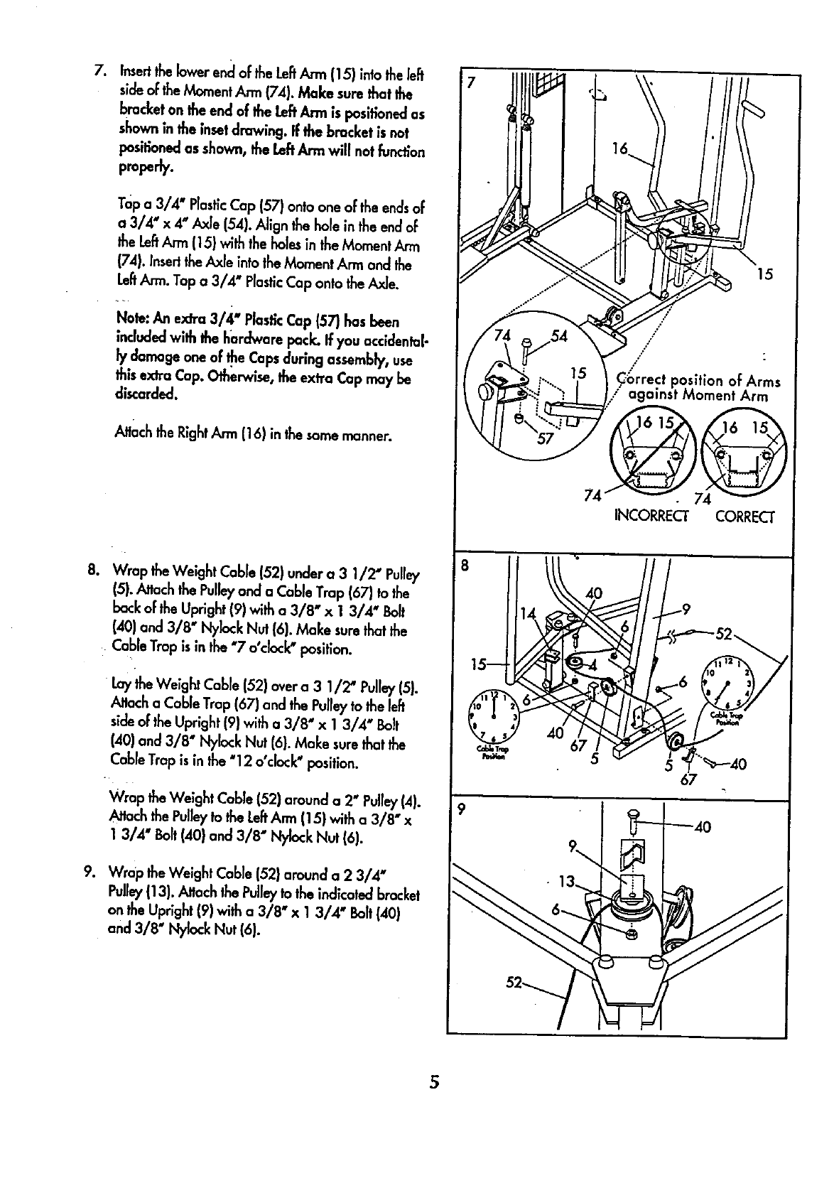
. Insertthelowerenc[of the LeftArm (15) intotheleft
side of the Moment Ann (74). Make sure that the
bracket on the end of the LeftArm is positionedas
shown in the insetdrawing. If the bracket isnat
positioned as shown, the LeftAnn willnotfunction
properly.
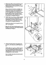
Top a 3/4" PlasticCap (57) onto one of the endsof
a 3/4" x 4" Axle (54). Align the hole in theend of
the LeftArm (15} with the holes in the Moment
(74). Insert theAxle into theMoment Arm and the
LeftArm. Tap a 3/4' PlasticCap onto the Axle.
Nole: An extra 3/4" Plastic Cap (57) has been
included with the hardware pock. If you accldenlal-
ly damage one of He Capsduring assembly, use
this extra Cap. Otherwise, the extra Cap may be
discarded.
Attachthe RightArm (16) in thesame manner.
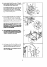
8. Wrap the Weight Cable (52) under a 3 1/2" Pub/
15).Attach thePulleyand a Cable Trap (67) tothe
backof the Upright (9) with a 3/8" x 1 3/4" Bolt
(40) and 3/8" Nylock Nut (6). Make surethat the
CableTrap is in the "7 o°dock" position.
Laythe Weight Cable (52) over a 3 1/2' Pulley(51.
_toch o Cable Trap (67) and the Pulley to the I_
sideof theUpright (9) with a 3/8" x 1 3/4" Bolt
(40) and 3/8" Nylock Nut (6). Make surethat the
CableTrap isin the "12 o'cbck" position.
Wrap the Weight Cable (52) around a 2" Pulley(4).
h'_ch thePulleyto theLeftAnn (15} with a 3/8" x
1 3/4" Bolt (40} and 3/8" Nylock Nut (6).
9. Wrap the Weight Cable (52} around a 2 3/4"
Pulley1131.,_ach the Pulleyto the indicatedbracket
on the Upright 19)with a 3/8" x 1 3/4" Bolt(40)
and 3/8" Ny!ock Nut (6).
8
9
15
,/"
/ [
/
C_rrect position of Arms
against Moment Arm
74
INCORRECI" CORRECT
5