


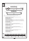

24
S T E P
9
Be careful to assemble all components in the sequence they are presented.
NOTE:
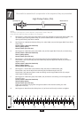
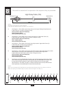
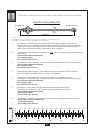
All Pulleys in this step are 110mm diameter, except where noted in Step 9B.
Leave all pulley bolts hand tight until Step 13 is completed.
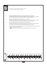
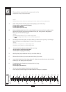
0 10 20 30 40 50 60 70 80 90 100 110 120 130 140 150
0 1 2 3 4 5 6
MM
Inch
A.
B.
C.
D.
E.
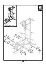
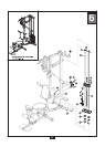
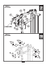
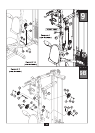
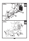
See Diagram 1. Route Cable (107) through Upper Floating Pulley Bracket (V).
Route Cable (107) around Pulley (B3) and install Pulley (B3) as shown in Diagram 2 using :
One 53 (10mm x 45mm hex head bolt)
Two 60 (10mm washer)
One 70 (10mm nylon lock nut)
One 53 (10mm x 45mm hex head bolt)
Two 60 (10mm washer)
One 70 (10mm nylon lock nut)
See Diagram 1. Route Cable (107) through Ab Crunch Pulley Bracket (W).
Route Cable (107) around Pulley (B2) and install Pulley (B2) as shown in Diagram 2 using:
One 53 (10mm x 45mm hex head bolt)
Two 60 (10mm washer)
One 70 (10mm nylon lock nut)
See Diagram 1. Route the stamped eye end of the Low Pulley Cable (107) through Upper Main
Frame (D) and install 90mm diameter Pulley (B1) under Cable (107) as shown in Diagram 2 using:
One 52 (10mm x 95mm hex head bolt)
Two 14 ( pulley spacer)
One 70 (10mm nylon lock nut)
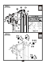
See Diagram 1A. Attach Short Cable (103) to Lower Main Base Frame (A) using:
One 98 (10mm x 110mm hex head bolt)
Two 60 (10mm washer)
One 70 (10mm nylon lock nut)
Attach the other end of Cable (103) to the hook on the bottom of Ab Crunch Pulley Bracket (W)
and secure with Acron Cap Nut (40).
2670 mm
Ball Stop End
Stamped Eye End
Low Pulley Cable (107)
Stamped Eye End
Stamped Eye End
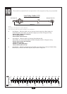
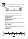
Short Cable (103)
700 mm
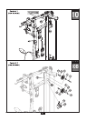
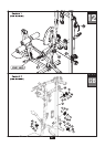
See Diagram 1. Route Cable (107) up through the two floating pulley Bracket (AB).
Install Pulley (B4) over Cable (107) as shown in Diagram 2 using :