


22
S T E P
8
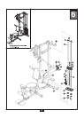
Be careful to assemble all components in the sequence they are presented.
NOTE:
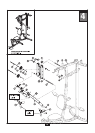
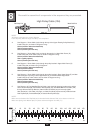
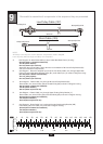
All Pulleys in this step are 110mm diameter.
Leave all pulley bolts hand tight until Step 13 is completed.
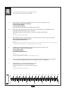
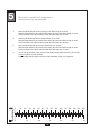
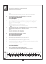
0 10 20 30 40 50 60 70 80 90 100 110 120 130 140 150
0 1 2 3 4 5 6
MM
Inch
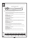
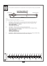
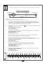
Ball Stop End
Metal Ball End
High Pulley Cable (104)
4260 mm
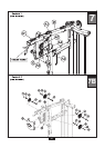
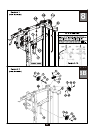
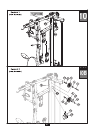
A. See Diagram 1. Route Cable (104) through the top of the Upper Floating Pulley Bracket (V).
Install Pulley (A7) as shown in Diagram 2 using:
One 53 (10mm x 45mm hex head bolt)
Two 60 (10mm washer)
One 70 (10mm nylon lock nut)
One 70 (10mm nylon lock nut)
B. See Diagram 1. Route Cable (104) up through the opening in Upper Main Frame (D).
Install Pulley (A8) under Cable (104) as shown in Diagram 2 using :
One 52 (10mm x 95mm hex head bolt)
Two 14 (pulley spacer)
One 70 (10mm nylon lock nut)
C. See Diagram 1. Route Cable (104) through the pulley bracket in Upper Main Frame (D).
Install Pulley (A9) as shown using in Diagram 2:
One 53 (10mm x 45mm hex head bolt)
Two 60 (10mm washer)
D. See Diagram 1. Route Cable (104) through the pulley bracket in Rear Upper Beam (E) and then
down through the opening in Rear Upper Beam (E), and down toward weight stack.
Install Pulley (A10) under Cable (104) as shown in Diagram 2 using :
One 53 (10mm x 45mm hex head bolt)
Two 60 (10mm washer)
One 70 (10mm nylon lock nut)
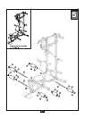
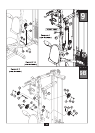
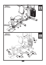
E. See Diagram 1A. The Metal Ball End of Cable (104) should be hanging just above the weight
stack. Remove Bolt (59) from Selector Rod Top Bolt (34), slide Metal Ball End of Cable (104)
through Selector Rod Top Bolt (34). Attach Cable End Shaft (33) and securely tighten
Allen Screw (67). Pull Cable (104) tight, so Cable End Shaft (33) fits securely inside Selector
Rod Top Bolt (34). Reinstall Bolt (59) in Selector Rod Top Bolt (34).
NOTE:
Make sure the Selector Rod Top Bolt (34) is threaded inside Selector Rod (31) at least one half inch.
Make sure Spring Lock Washer (63) is in place and wrench tighten Jam Nut (71).