


Groundsmaster 4000--D/4010--D Hydraulic SystemPage 4 -- 25
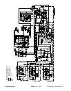
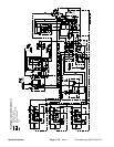
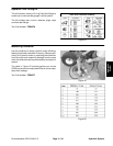
Engine Cooling Fan Circuit
A four section gear pump is coupled to the piston (trac-
tion) pump. Thegear pumpsection farthest from the pis-
ton pump supplies hydraulic flow for the engine cooling
fan circuit (Fig. 15).
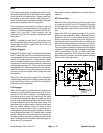
The fan drive manifold controls the operation of the hy-
draulic motor that drives the engine cooling fan in addi-
tion to including the flow divider for the steering and
lift/lower circuits. The fan drive manifold controls the
speed and direction of the fan motor based on electrical
output from the TEC --5002 controller.
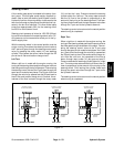
Oil flow from the gear pump to the cooling fan motor is
controlled by the proportional relief valve (PRV) in the
fan drive manifold. This v alve adjusts fan circuit pres-
sure and flow based on a PWM (Pulse Width Modula-
tion)signalfromthe TEC--5002 controller.The controller
uses engine coolant and hydraulic oil temperatures as
inputs to determine the proper PWM signal for the (PRV)
valve. The fan circuit flow determines the speed of the
cooling fan motor and thus, the speed of the cooling fan.
If the fan motor is stalled for any reason, the manifold
proportional relief valve (PRV) has a secondaryfunction
as a circuit relief to limit fan motor pressure to 3000 PSI
(207 bar).
When the engine is shut off, the over--running inertia
load of the fan blades keeps driving the fan motor and
turnsitinto a pump. The check valve (CV) in the fandrive
manifold will open to keep the motor circuit full of oil so
the fan motor will not cavitate.
Forward Direction Fan Operation
Oil flow from thegear pumpis sent through thede--ener-
gized fan manifold solenoidvalve (S1) to rotatethe cool-
ing fan motor. Return flow from the motor re--enters the
manifold (port M2), through the de --energized solenoid
valve (S1), outof the manifold (portT) and then is routed
through the oil cooler and oil filter.
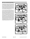
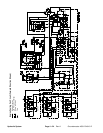
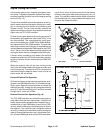
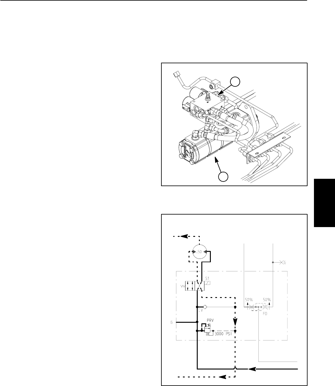
Reverse Direction Fan Operation (Fig. 16)
The TEC--5002 controller can reverse the cooling fan to
clean debris from the rear intake screen. If hydraulic oil
and/or engine coolant temperatures increase to an un-
suitable level, a high PWM signal is sent to the (PRV)
valve to slow the cooling fan and direct pump oil flow to
the r eservoir. The controller then energizes solenoid
valve(S1)inthe fan drivemanifoldtoreverse cooling fan
motor oil flow so that the motor runs in the reverse direc-
tion. A lower PWM signal is sent to the PRV valve allow-
ing oil flow to return to the fan motor but in the reverse
direction causing the motor and cooling fan to run in r e-
verse. The controller determines the length of time that
the fan should be run in reverse before fan rotation is re-
turned to the forward direction.
1. Gear pump 2. Fan drive manifold
Figure 15
1
2
Figure 16
FAN DRIVE
MANIFOLD
M1 M2 L
P1 P2T
FROM GEAR PUMP
TO OIL COOLER
TO RESERVOIR
TO LIFT/LOWER
CIRCUIT
TO STEERING
CIRCUIT
REVERSE DIRECTION SHOWN
(ENERGIZED)
Hydraulic
System