


Groundsmaster 4000--D/4010--D Hydraulic SystemPage 4 -- 69
Procedure for Engine Cooling Fan Circuit Gear
Pump Flow Test
1. Make sure hydraulic oil is at normal operating tem-
perature by operating the machine under load for
approximately ten (10) minutes. Make sure the hydrau-
lic tank is full.
2. Park machine on a level surface with the cutting
decks lowered and off. Make sure engine is off and the
parking brake is applied. Raise and support seat to gain
access to the gear pump.
CAUTION
Prevent personal injury and/or damage to equip-
ment. Read all WARNINGS, CAUTIONS and Pre-
cautions for Hydraulic Testing at the beginning
of this section.
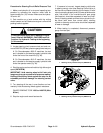
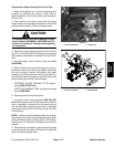
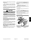
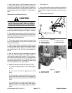
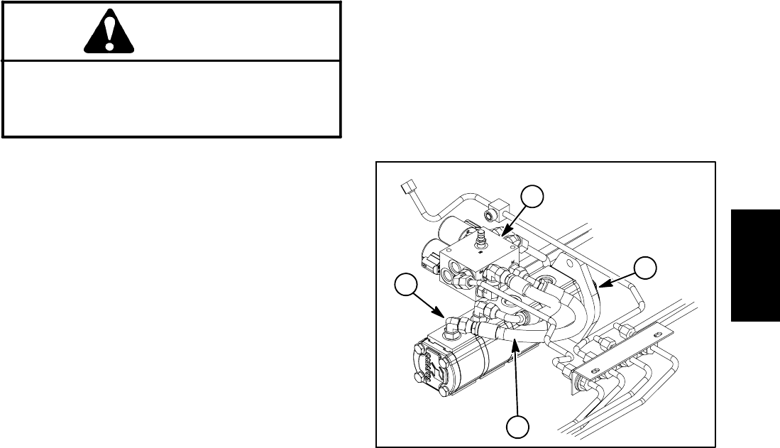
3. With the engine off and cutting decks lowered, dis-
connect the hydraulic hose from the 90
o
fitting in the last
gear pump section which supplies the engine cooling
fan circuit (Fig. 54).
IMPORTANT: Make sure that the oil flow indicator
arrow on the flow gauge is showing that the oil will
flow from the pump section, through the tester and
into the hydraulic hose.
4. Install tester (flow and pressure) in series between
the fitting and the disconnected hose. Make sure the
flow control valve on tester is fully open.
IMPORTANT: The pump is a positive displacement
type. If pump flow is completely restricted or
stopped, damage to the pump, tester or other com-
ponents could occur.
5. Start the engine and move throttle to high idle speed
(2870 RPM). DO NOT engage the cutting decks.
6. While watching tester pressure gauges, slowly close
tester flow control valve until 1000 PSI (69 bar) is ob-
tained on gauge. Verify engine speed continues to be
2870 RPM.
GAUGE READING TO BE: Flow approximately 7
GPM (26 LPM) at 1000 PSI (69 bar).
NOTE: If engine speed drops below 2870 RPM, pump
flow will decrease.
7. Open tester flow control valve, stop engine and re-
cord test results.
8. If a pressure of 1000 PSI (69 bar) could not be ob-
tained or flow is lower than 6GPM(23LPM), check for
restriction in pump intake line. If intake line is not re-
stricted, consider that gear pump section for engine
cooling fan circuit is worn or damaged.
9. When testing is complete, remove tester and recon-
nect hose to pump fitting.
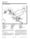
1. Gear pump
2. Fan drive manifold
3. Engine cooling hose
4. 90
o
fitting
Figure 54
1
2
3
4
Hydraulic
System