


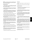
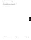

Groundsmaster 4000--D/4010--D Hydraulic SystemPage 4 -- 85
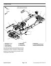
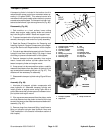
Transport Cylinder
A transport cylinder is included in the traction circuit to
reduce traction pump control arm movement when op-
erating in Hi speed (2WD). This reduced control arm
movement limits pump swash plate rotation to prevent
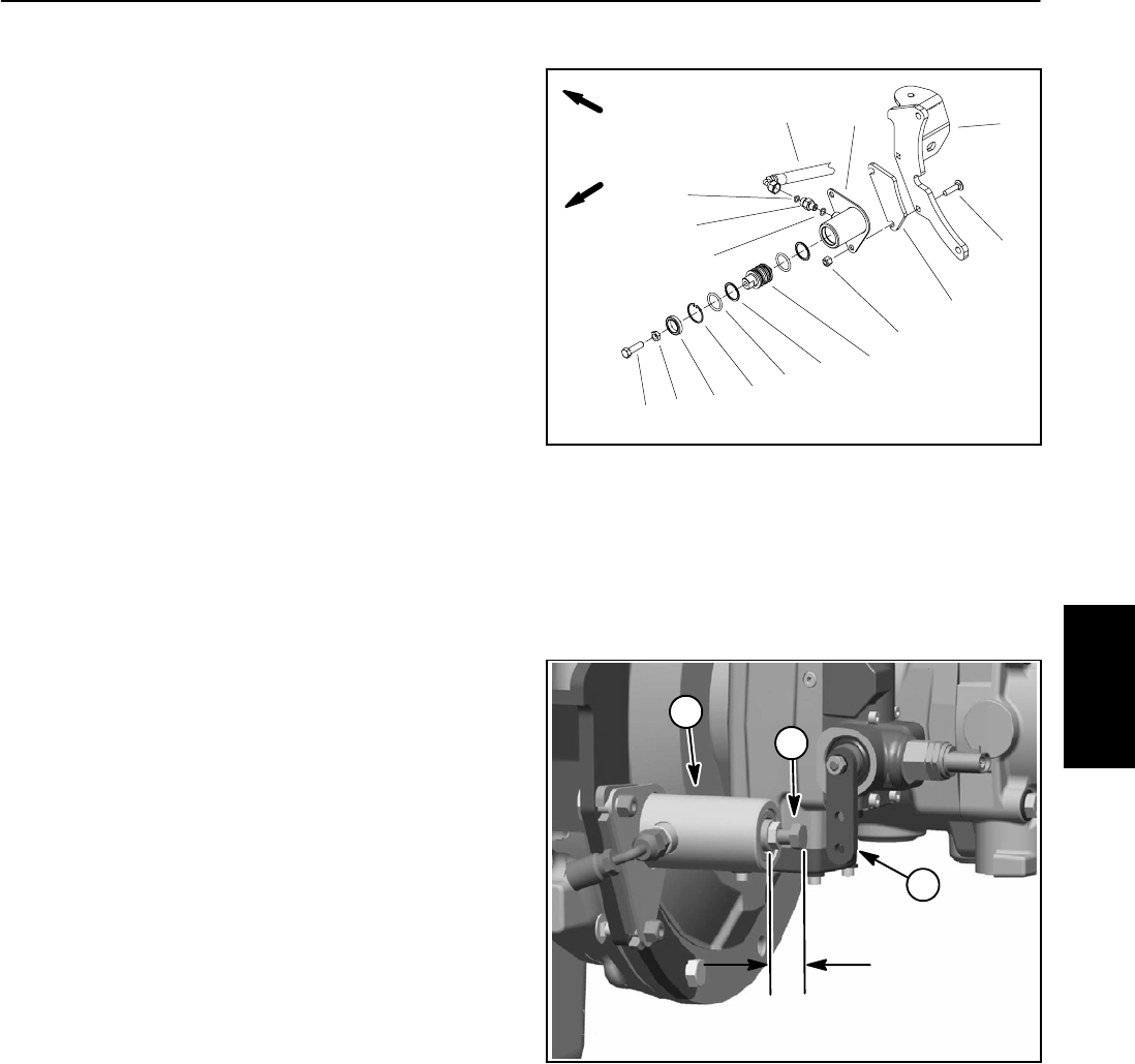
excessive transport speed. The transport cylinder is at-
tached to the forward, right side engine mount (Fig. 66).
Disassembly (Fig. 66)
1. Park machine on a level surface, lower cutting
decks, stop engine, apply parking brake and remove
key from the ignition switch. Raise and support hood.
2. To prevent contamination of hydraulic system during
removal, thoroughly clean exterior of pump assembly.
3. Read the General Precautions for Removing and
Installing Hydraulic System Components at the begin-
ning of the Service and Repairs section of this chapter.
4. Putadrainpan below the transport cylinder.R emove
hydraulic hose from cylinder fitting. Put plugs in hose
and fitting to prevent contamination of the system.
5. Remove transport cylinder assembly from engine
mount. Locate and remove cylinder spacer from be-
tween transport cylinder and engine mount.
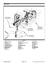
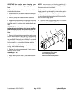
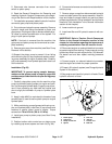
6. If cap screw is to be removed from piston, carefully
measure the distance from the piston to the end of the
cap screw before loosening the jam nut (Fig. 67). This
distance will be necessary for assembly.
7. Disassemble transport cylinder using Figure 66 as a
guide.
Assembly (Fig. 66)
1. Lubricate all transport cylinder components with
clean hydraulic oil. Assemble transport cylinder and
install cylinder to engine mount using Figure 66 as a
guide. Make sure that cylinder spacer is between trans-
port cylinder and engine mount.
2. If the cap screw was removed from the piston, make
sure that distance from the piston to the end of the cap
screw is the same as the distance measured before dis-
assembly (Fig. 67).
3. Remove plugs from hose and fitting. Install hose to
fitting on transport cylinder (see Hydraulic Hose and
Tube Installation in the General Information section of
this chapter).
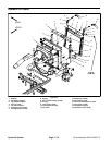
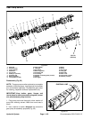
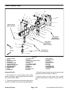
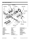
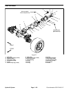
Figure 66
1. Carriage screw (2 used)
2. Cylinder spacer
3. Transport cylinder
4. Lock nut (2 used)
5. Piston
6. Backup ring (2 used)
7. O--ring (2 used)
8. Retaining ring
9. Seal
10. O--ring
11. Fitting
12. O--ring
13. Hydraulic hose
14. RH engine mount
15. Jam nut
16. Cap screw
FRONT
RIGHT
2
3
4
8
6
7
1
5
9
10
11
12
14
13
15
16
1. Transport cylinder
2. Cap screw
3. Pump control arm
Figure 67
1
2
3
MEASURE
DISTANCE
Hydraulic
System