


Groundsmaster 4000--D/4010--DPage 5 -- 2Electrical System
General Information
Operator’s Manual
The Operator’s Manual provides information regarding
the operation, general maintenance and maintenance
intervals for your Groundsmaster machine.Refer to that
publication for additional information whenservicing the
machine.
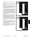
Toro Electronic Controllers (TEC)
Groundsmaster4000--D and 4010--Dmachinesusetwo
(2) Toro Electronic Controllers (TEC) to manage ma-
chine electrical functions. The controllers are micropro-
cessor controlled that sense the condition of various
switches (inputs) and direct electrical power to control
appropriate machine functions (outputs) based on the
inputs. Communication between the two Toro control-
lers is provided with a CAN--bus system. The status of
inputs to the controllers as well as outputs from the con-
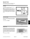
trollers can be monitored with the Diagnostic Display
(see Special Tools in this chapter).
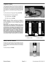
The controllers appear identical but they are different in
terms of the connectors and internal hardware. They are
arranged in ”master / slave” configuration and therefore
cannotbe interchanged.TheTEC--5002 master control-
ler is responsible for powering up the TEC--5001 slave
controller. The TEC--5002 also controls the engine start
circuit.
IMPORTANT: Before performingany welding on the
machine, disconnect the battery cables from the
battery, disconnect the wire harness connector
from both of the TECcontrollers and disconnect the
terminal connector from the alternator. These steps
will prevent damage to the machine electrical sys-
tem.
CAN--bus Communications
The two (2) TEC controllers (TEC--5001 and
TEC--5002) used on the Groundsmaster 4000--D and
4010--D communicate with each other on a CAN--bus
system. Using thissystem allows the tractionunit to fully
integrate all the different electrical components of the
machine and bring them together as one. The CAN--bus
system reduces the number of electrical components
and connections used on the machine and allows the
number of wires in the wire harness to be significantly
reduced.
CAN identifies the Controller Area Network that is used
between the controllers on the Groundsmaster. Two (2)
specially designed, twisted cables form the bus. These
wires provide the data pathways between the control-
lers (TEC--5001 and TEC--5002) used on the machine.
The engineering term for thesetwo (2) cables are CAN--
high and CAN--low. At the ends of the twisted pair of bus
cables are 120 ohm termination resistors.
Each of the components that is controlled by the CAN--
buslinkonly needs four (4)wirestooperate and commu-
nicate to the system: CAN --high, CAN--low, B+ (power)
and ground.
Electrical Drawings
The electrical schematic and wire harness drawings for
Groundsmaster 4000--D and 4010--D machines are lo-
cated in Chapter 10 -- Foldout Drawings.