


Groundsmaster 4000--D/4010--D Page 7 -- 7 Chassis
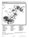
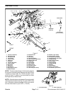
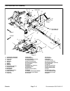
Removal (Fig. 5)
1. Park machine on a level surface, lower cutting
decks, stop engine, apply parking brake and remove
key from the ignition switch.
2. Remove side deck from lift arm (see Side Cutting
Deck Removal in Chapter 8 -- Cutting Decks).
3. Remove side deck reararm assemblyfrom pivot hub
(see Side Deck Rear Arm Assembly Removal in this
section).
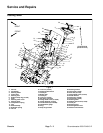
4. Remove lift cylinderpin (item3) thatsecuresliftcylin-
der to lift arm.
5. Drive out slotted roll pin (item 15) that retains lift arm
pivot shaft. Discard roll pin.
6. Support lift arm and pull lift arm pivot shaft from lift
armand frame.Locate and remove thrust washers (item
5) during pivot shaft removal.
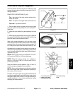
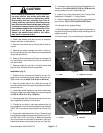
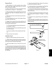
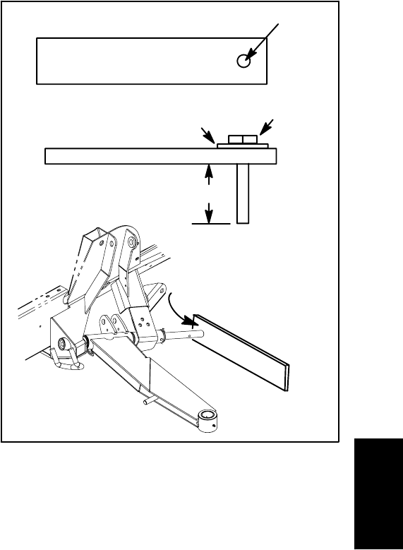
A. If pivot shaft is difficult to remove, fabricate a pull-
er as shown in Figure 7.
B. Attachpuller to end of pivotshaft w ith thepictured
bolt and flat washer.
C. Drivepivotshaft from lift arm and framewith ham-
mer.
7. Remove lift arm from machine.
Installation (Fig. 5)
1. Apply anti--seize lubricant to lift arm pivot shaft.
2. Positionliftarmtoframe withthrustw ashers properly
placed (Fig. 5). Slide pivot shaft into frame and lift arm
until roll pin holes in shaft and frame align.
3. Install new slotted roll pin to secure lift arm pivot
shaft.
4. If pivot hub was r emoved from pivot shaft, slide pivot
hub onto shaft. Apply Loctite#242 (or equivalent) to cap
screw threads and secure pivot hub with washer and
cap screw. Torque cap screw from 77 to 96 ft--lb (105
to 130 N--m).
5. Align lift cylinder with lift arm. Secure lift cylinder to
lift arm with lift cylinder pin (item 3).
6. Install side deck rear arm assembly (see Side Deck
Rear Arm Assembly Installation in this section).
7. If sensing plate (item 26) was removed from lift arm,
secure plate so it is rotated as far as possible toward
center of machine.
8. Position and install side cutting deckto machine (see
Side Cutting Deck Installation in Chapter 8 -- Cutting
Decks).
9. Lubricate lift arm grease fittings after assembly is
complete.
10.After assembly is completed,raise and lowerthe cut-
ting deck to verify that hydraulichoses andfittings do not
contact anything.
Figure 7
3” x 12” (3/8” to 1/2” thick) plate steel
9/16” hole
1/2” -- 13 UNC bolt
Flat washer
1” to 1 1/8”
Use hammer to drive
pivot shaft from lift arm
Chassis