


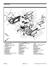
Groundsmaster 4000--D/4010--D Page 7 -- 9 Chassis
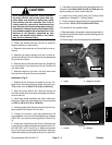
Rear Arm Removal (Fig. 8)
1. Park machine on a level surface, lower cutting
decks, stop engine, apply parking brake and remove
key from the ignition switch.
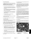
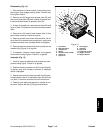
2. Removehairpinandclevis pin that connects damper
link to cutting deck (Fig. 9).
3. Remove cap screw and lock nut that secures rod end
of rear arm to cutting deck. Locate and remove spacer
from each side of rod end.
4. Remove lock nut and lock washer that secures rear
arm pivot shaft. Slide pivot shaft from hub and rear arm.
Remove rear arm assembly from machine.
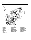
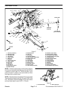
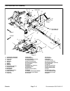
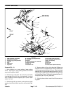
Rear Arm Disassembly (Fig. 8)
1. Disassemble rear arm assembly using Figure 8 as a
guide.
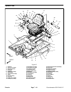
Rear Arm Assembly (Fig. 8)
1. Slide large flat washer, spring, plastic bearing, sec-
ond large flat washer and small flat washer onto spring
shaft. Loosely secure components to shaft with one jam
nut.
2. Slide the straight bushing and plate onto other end
of spring shaft.
3. While holding flats on end of spring shaft, rotate jam
nut (on other end of assembly) until components are
snug but spring is not compressed.
4. Insert assembly into rear arm housing.
5. From open end of rear arm housing, insert a 3/4”
socket onto spring shaft jam nut. Tighten jam nut fully.
6. Mount plate to rear arm housing with two (2) cap
screws and lock nuts. Grasp end of spring shaft. Push
inward and pull outward on shaft to determine endplay
in assembly.
IMPORTANT: All endplay must be removed from as-
sembly to allow proper operation and ensure long life.
7. Loosen jam nut, 1/2 turn at a time, until all endplay
in shaft is removed.
8. Remove two (2) cap screws and nuts securing plate
to rear arm housing. Remove spring shaft assembly
from housing.
9. Thread remaining jam nut onto end of spring shaft
and, while retaining inner jam nut to prevent it from mov-
ing, torque outer jam nut from 22 to 28 ft--lb (30 to 37
N--m) to lock adjustment.
10.Thoroughly pack spring with grease. Install s pring
shaft assembly into housing and secure plate with four
(4) cap screws and lock nuts.
11.Thread rod end (item 8) with jam nut (item 9) into end
of spring shaft. Do not tighten jam nut at this time.
12.If rod ends (item 31) were removed from damper
(item 30), apply Loctite #271 (or equivalent) to damper
shaft threads before installing rod ends.Secure damper
to bellcrank and rear arm with cap screws and lock nuts.
Torque fasteners from 270 to 330 in--lb (31 to 37 N--m).
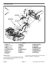
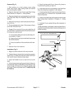
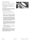
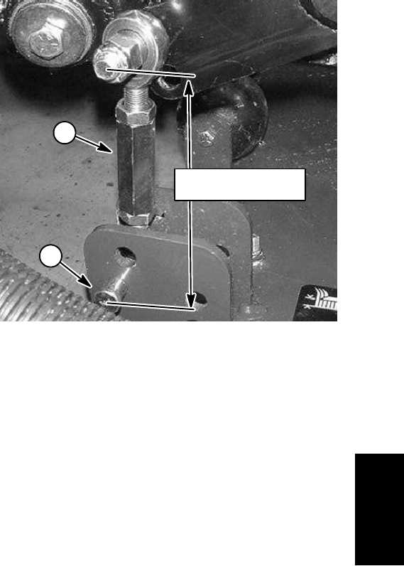
13.If damper link was disassembled, adjust the length
of the link from 5.295” to 5.445” (134.5 to 138.3 mm)
(Fig. 9).
14.If damper springs (item 37) were removed, tighten
lock nuts so that bushings (item 36) are free to rotate.
1. Damper link assembly 2. Clevis pin
Figure 9
1
2
5.295” to 5.445”
(134.5 to 138.3 mm)
Chassis