


Page viii
Step Assembly.............................................................................................. 54
Step Chain Assembly ................................................................................... 55
Upper (and Lower) Sprocket Assembly ....................................................... 57
Cable Assembly ............................................................................................ 59
Transmission Assembly................................................................................ 60
Alternator Assembly ..................................................................................... 61
Relay/Resistor Assembly ............................................................................. 62
GROUNDING INSTRUCTIONS ......................................................................... 64
FCC COMPLIANCE............................................................................................. 65
CANADIAN DOC CLASS A COMPLIANCE ..................................................... 65
APPENDICES
Important Phone Numbers........................................................................... 66
Figures 6 - 12 ................................................................................................ 67
LIST OF TABLES
Table 1. Dimensions and Specifications for the
StairMaster
®
7000 PT Exercise System ................................................ 3
Table 2. Fitness Rating Norms ..................................................................... 14
Table 3. Recommended Preventive Maintenance Schedule .................... 35
LIST OF ILLUSTRATIONS
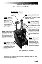
Figure 1: Correct Exercise Position ................................................................ 9
Figure 2: Transmitter Belt ............................................................................. 13
Figure 3: The Stepmill 7000 PT Console ..................................................... 14
Figure 4: StairMaster Fitness Protocol........................................................ 24
Figure 5: Grounding System......................................................................... 64
Figure 6: Side Cover and Handrail Assemblies........................................... 67
Figure 7: Cover Fasteners ............................................................................ 68
Figure 8: Step Assembly .............................................................................. 69
Figure 9: Step Chain and Sprocket Assemblies ......................................... 70
Figure 10: Transmission and Alternator Assemblies .................................. 71
Figure 11: Wiring Diagram ........................................................................... 72
Figure 12: Relay Board ................................................................................. 73
CONTENTS