


Page 44
SPEED CONTROL PROBLEMS
4. Replace or exchange the console with another console you know is
good and retest the machine.
B. Check the relay assembly circuit board while the console displays "SELECT
WORKOUT." You will need an assistant to complete the test of the
relay assembly circuit board.
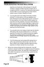
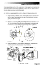
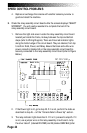
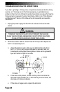
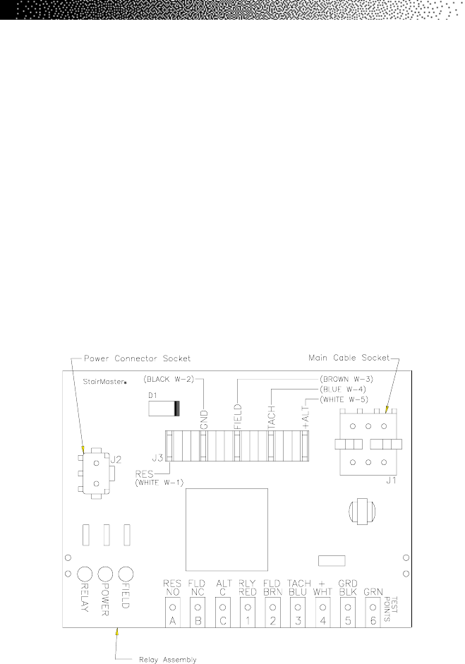
1. Remove the right side cover. Locate the relay assembly circuit board
located just inside the frame, midway between the top and bottom
steps (refer to Wiring Diagram). There are three red indicator lights
along the bottom edge of the circuit board. They are labeled, from top
to bottom: Field, Power, and Relay. Ensure the black and white wire
power connector (labeled J2 on the relay assembly circuit board) is
securely connected to the relay assembly circuit board (refer to Figure
Below).
2. If the Power light is lit, go to step #3. If it is not, perform the tests as
described in step 4b - c of the “Console Fails to Power Up” section.
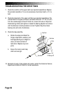
3. The relay indicator light should be lit. If it is lit, proceed to step #5. If it
is not, use a jumper wire on the relay assembly circuit board. Jump
the silver tabs #1 (labeled RLY/RED) and #5 (labeled GRD/BLK) (refer