


Page 45
SPEED CONTROL PROBLEMS
to Figure on page. 34). The relay indicator should light up. If it does, go
to step #4. If the relay indicator does not light up, the relay assembly
circuit board must be replaced. Replace the relay assembly circuit
board and retest the machine.
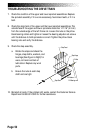
4. You must check the cable assembly for continuity if the relay indicator
lit up when you jumped tabs #1 and #5.
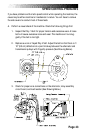
a. Unplug the main cable from the position labeled J1 on the relay
assembly circuit board. Disconnect the console cable from the
back of the console. Set your multimeter to the continuity check
mode; on most meters, this will be the resistance or ohms setting.
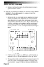
b. Place one lead of the multimeter on pin #1 at the console
connector end of the console cable (refer to Wiring Diagram).
Place the other lead on pin #1 at the end of the main cable you
disconnected from the relay assembly circuit board. You will get a
reading of near zero ohms if there is continuity in the cable
assembly.
c. Check continuity in both ends of the main cable assembly at pin
#5.
d. If there is no continuity in the cable assembly at either pin,
replace the cable assembly and retest. If there is continuity in the
cable assembly at both pins and the relay resistor indicator is not
lit, the console is inoperable and must be replaced.
5. Have your assistant step on the staircase (leave the console in the
ATTRACT mode) while you check the field indicator light. It should be
flickering. If it is and you still have a speed control problem, go to step
#6.
If it is not flickering, ensure the following: the console cable is
connected to the console; the console/main cable connection is
secure; the connector at position J1 on the relay assembly circuit
board is securely connected; that there is continuity in the cable
assembly. To check for continuity: