


Page 37
TROUBLESHOOTING THE ELECTRICAL SYSTEM
2. Verify that the AC wall outlet is supplying the correct power in one of
two ways: a) Use a voltmeter to verify that the AC line voltage is
between 108 and 130 VAC (or between 208 and 240 VAC, if applicable)
at the AC wall outlet; or b) Plug in an alternate AC-powered device (a
lamp, for example). If the AC wall outlet is supplying the correct power,
proceed to step #3. If the voltage is outside the range or if the device
does not work when plugged into the AC wall outlet, consult an
electrician for further assistance and then retest the AC wall outlet.
3. Plug the AC power cord into the wall outlet and proceed to the next
section.
C. Verify DC power.
1. Make sure that the AC power cord is plugged in and that the AC wall
outlet is delivering the proper voltage.
2. The indicator light should be lit. If it is, proceed to step #3. If the
indicator light is still not lit, replace the power supply and test the new
power supply.
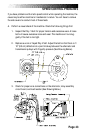
3. Disconnect the cable from the DC power connector located on the
bottom cover. Use a DC voltmeter to verify 12-19 VDC at the end of
the DC cable. Pin #1 is negative and pin #2 is positive. Proceed to step
#4 if the VDC is within the range. Replace the power supply if the VDC
is outside the range and test the new power supply.
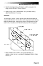
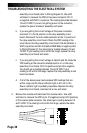
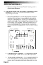
4. Remove the right side cover. Reconnect the DC power cable to the
machine. Locate the relay/resistor circuit board located just inside the
frame, midway between the top and bottom steps (refer to Wiring
Diagram 1). There are three red indicator lights along the bottom edge
of the relay assembly circuit board. They are labeled, from top to
bottom: Field, Power, and Relay. Ensure the black and white wire
power connector (labeled J2 on the relay resistor circuit board) is
securely connected to the relay resistor circuit board.
a. The Power light should be lit. If it is, go to step #5. If it is not,
disconnect the power connector from the J2 position on the relay