


11
9
104
111
Console Assembly
116
1
16
1
06
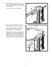
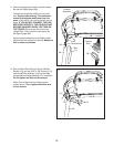
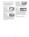
10. Identify the Right Handrail (101), which is
marked “Right.” Remove the tie from the Right
Handrail. If necessary, press the M8 Cage Nut
(34) back into place.
Hold the Right Handrail (101) near the console
assembly. Route the console wire around the
side of the Right Handrail as shown, and
through the slot in the Right Handrail.
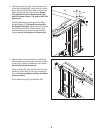
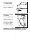
If necessary, adjust the Console Frame (111) to
align the holes in the Right Handrail (101) with
the holes in the Console Frame.
Attach the Right Handrail (101) to the Console
Frame (111) and the console assembly with two
M8 x 25mm Bolts (5), two M8 Star Washers
(10), an M5 x 16mm Screw (108), and a 1/4"
Star Washer (73). Make sure the console wire
is not pinched. Start the two Bolts and the
Screw, and then tighten all of them.
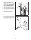
Attach the Left Handrail (not shown) as de-
scribed above. Note: There is not a wire on
the left side.
Tighten the #8 x 1" Screws (107). Be careful
not to overtighten the Screws.
101
108
5
111
Slot
Tie
10
10
73
Console
Wire
Console
Assembly
34
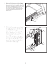
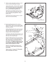
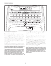
9. Set the console assembly face down on a soft
surface to avoid scratching the console.
L
oosen the four #8 x 1" Screws (107). Carefully
pivot the Console Frame (111) to the position
s
hown. Do not pivot the Console Frame too
far or you will break the ground wire.
Identify the Left and Right Accessory Trays
(104, 106). Attach the Accessory Trays to the
console assembly with eight M4.2 x 13mm
Screws (116).
Carefully pivot the Console Frame (111) back
down to the console assembly.
107
107