


29
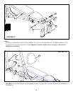
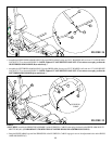
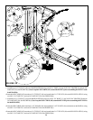
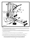
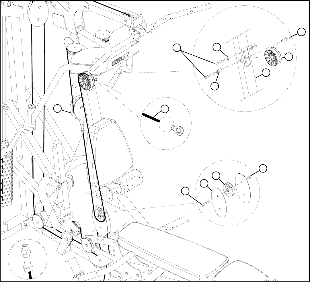
• Securely assemble the ball end of the AB CRUNCH CABLE (AY) and one 4-1/2” V-PULLEY (51) to the FRONT FRAME (E) using two
3/8 X 3-3/4” BOLTS (11), two 3/8 X 19/32” FLANGE SPACERS (42), two 3/8” WASHERS (23) and two 3/8” LOCKNUTS (28).
See FIGURE 31(a) (NOTE: The AB CRUNCH CABLE (44) should be routed underneath the retaing bolt as shown in FIGURE 31.)
STEP 31:
(a)
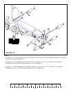
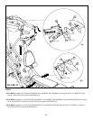
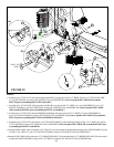
• Route the AB CRUNCH CABLE (AY) around one 3-1/2” PULLEY (49) and assemble the 3-1/2” PULLEY (49) to the PULLEY PLATES (L)
using one 3/8 X 1-3/4” BOLT (17) and one 3/8” LOCK NUT (28). See FIGURE 31(b)
• Screw the threaded end of the AB CABLE (AY) into the end of the FLOATING PULLEY BRACKET (W) .See FIGURE 31.
L
E
51
28
3/8 X 1-3/4” 17
3/8 X 3-3/4” 11
23
42
AY
W
49
28
(b)
FIGURE 31