


16
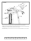
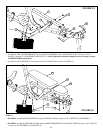
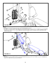
FIGURE 13
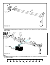
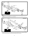
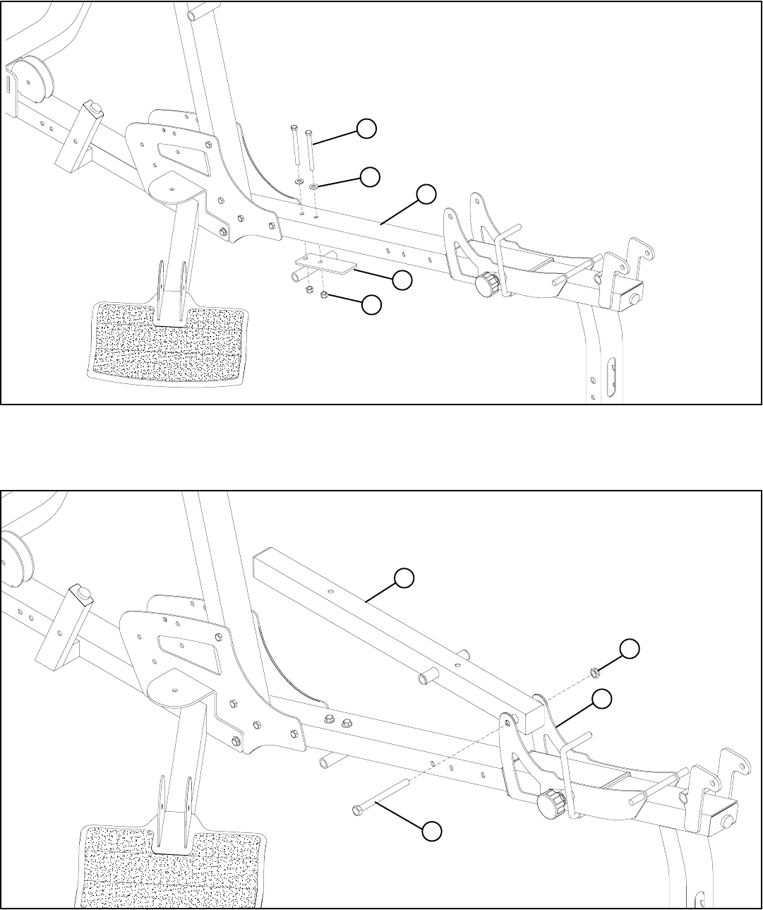
STEP 14:
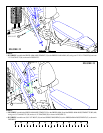
FIGURE 14
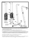
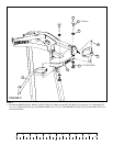
STEP 13:
• SECURELY assemble the PIVOT ASSEMBLY (AG) to the SEAT FRAME (AF) using two 3/8 X 2-3/4” BOLTS (15), two 3/8”
WASHERS (23) and two 3/8” LOCK NUTS (28) as shown in FIGURE 13.
15 3/8 X 2-3/4”
AF
23
AG
28
M
J
• Assemble the BENCH TUBE (J) to the SEAT ADJUST (M) using one 1/2 X 4-1/4” BOLT (4) and one 1/2” LOCK NUT (26). (Note:
Tighten this connection enough to remove excess play yet allow the BENCH TUBE to rotate freely.)
4 1/2 X 4-1/4”
26