


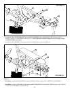
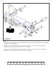
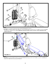
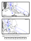
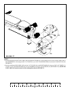
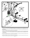
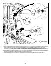
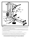
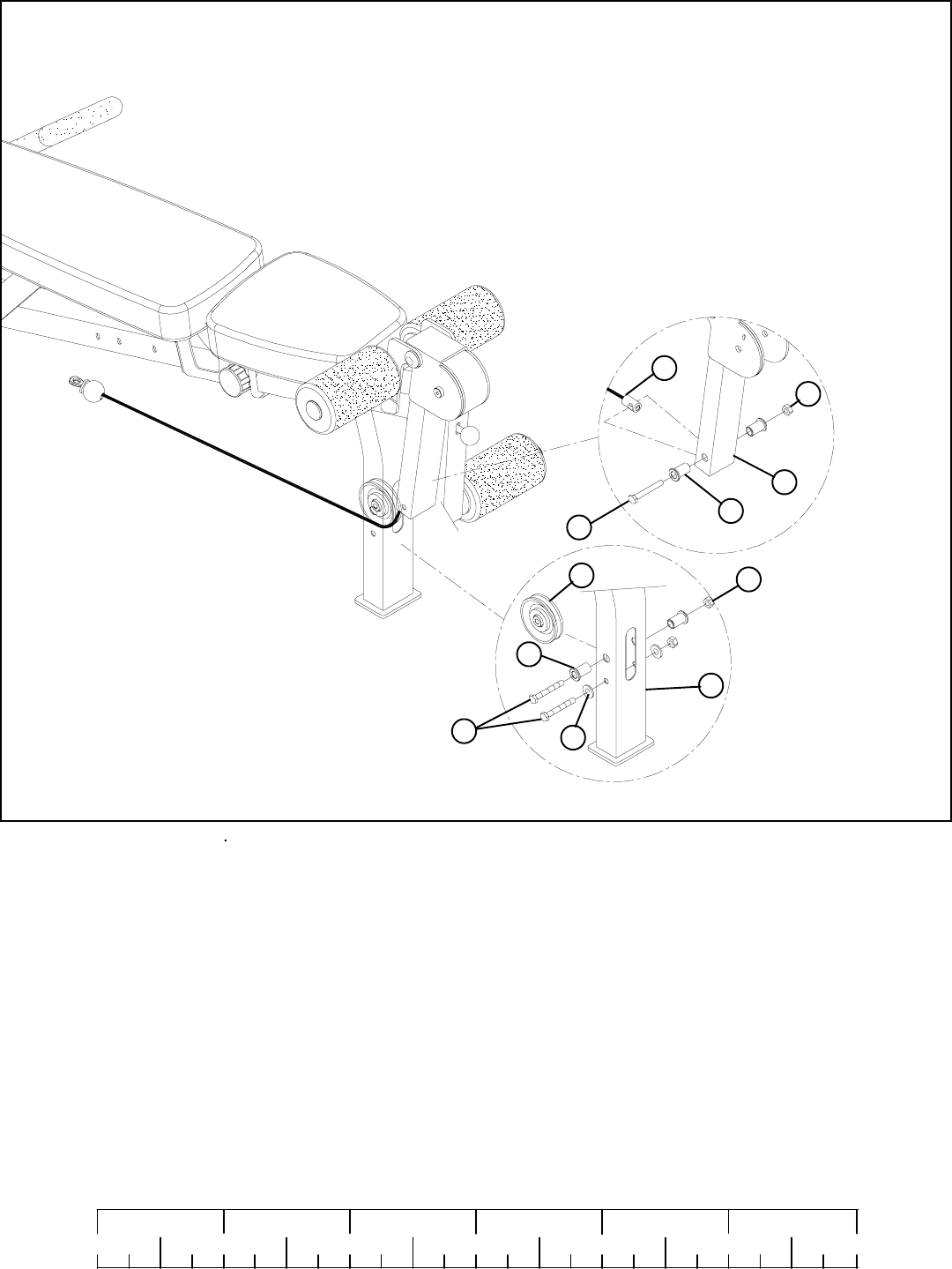
STEP 27:
FIGURE 27
• Route the threaded end of the LOW CABLE (AW) thru theSEAT FRAME (AF) and assemble the swivel end of LOW CABLE (AW) to
the LEG PEDESTAL (AD) using one 3/8 X 3-1/4” BOLT (13), two 15/16” FLANGE SPACERS (41) and one 3/8” LOCK NUT (28). See
FIGURE 27(a)
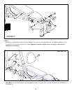
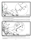
• Securely assemble the LOW CABLE (AW) and one 3-1/2” PULLEY (49) to the SEAT FRAME (AF) using two 3/8 X 3-3/4” BOLTS (11),
two 3/8 X 1-1/16” FLANGE SPACERS (40), two 3/8” WASHERS (23) and two 3/8” LOCKNUTS (28). See FIGURE 27(b). (NOTE: The
LOW CABLE (AW) must be routed over the retaining bolt as shown in FIGURE 27.)
23
40
49
28
41
AD
3/8 X 3-3/4” 11
3/8 X 3-1/4” 13
28
AW
25
0
1
2
345
6
1/2 1/2 1/2 1/2 1/2 1/2
AF
(a)
(b)