


24
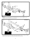
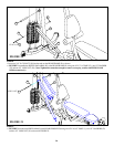
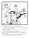
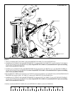
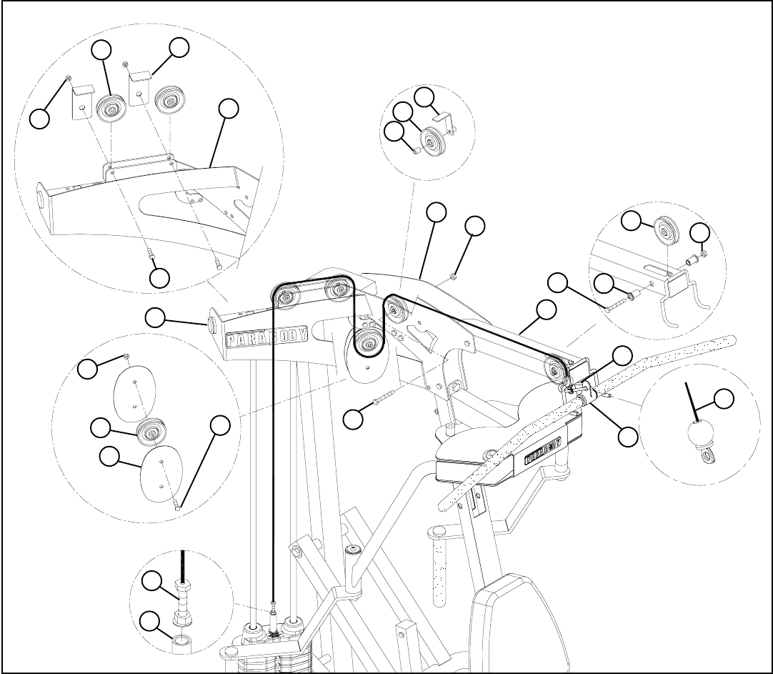
STEP 26:
• Assemble two 3-1/2” PULLEYS (49) to the RIGHT TOP ASSEMBLY (X) using two 3/8 X 2” BOLTS (16), two L CABLE RETAINER
(AA) and two 3/8” LOCK NUTS (28) as shown in FIGURE 26(b)
• Screw the long threaded end of the LAT CABLE (AV) into the end of the HEAD PLATE (AK) .See FIGURE 26(a)
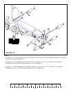
• Route the LAT CABLE (AV) around the pulleys in the RIGHT TOP ASSEMBLY (X) as shown in FIGURE 26. (NOTE: Make sure the
cable runs in the grooves of the pulleys.)
• IMPORTANT! Uncoil and straighten all CABLES in order to remove all twist prior to installation
FIGURE 26
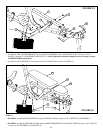
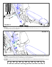
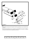
• Route the LAT CABLE (AV) around one 3-1/2” PULLEY (49) and assemble two FLOATING PULLEY PLATES (L) to the 3-1/2” PULLEY
(49) using one 3/8 X 1-3/4” BOLT (17) and one 3/8” LOCK NUT (28). See FIGURE 26(c)
• Route the LAT CABLE (AV) around one 4-1/2” PULLEY (50) and assemble the PULLEY to the RIGHT TOP ASSEMBLY (X) and the LEFT
TOP PLATE (Y) using one 3/8 X 3-3/4” BOLT (11), one 3/8 X 15/16” SPACER (30), one LONG “L” CABLE BRACE (Z) and one 3/8”
LOCK NUT (28). See FIGURE 26(d)
• Route the LAT CABLE (AV) around one 3-1/2” PULLEY (49) and assemble the PULLEY to the FRONT FRAME (E) using one 3/8 X 3-
3/4” BOLT (11), two 3/8 X 1-1/16” FLANGE SPACERS (40) and one 3/8” LOCK NUT (28). See FIGURE 26(e)
AA
X
3/8 X 2” 16
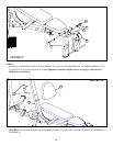
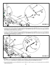
• Assemble the LAT BAR (AL) to the LAT CABLE using one SNAP LINK (39) as shown in FIGURE 26.
11 3/8 X 3-3/4”
3/8 X 1-3/4”
3/8 X 3-3/4” 11
AK
AV
L
49
28
AV
AL
39
E
40
28
49
28
30
50
Z
28
49
Y
X
17
(a)
(c)
(b)
(d)
(e)