


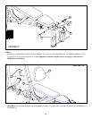
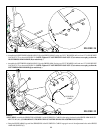
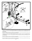
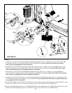
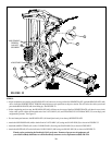
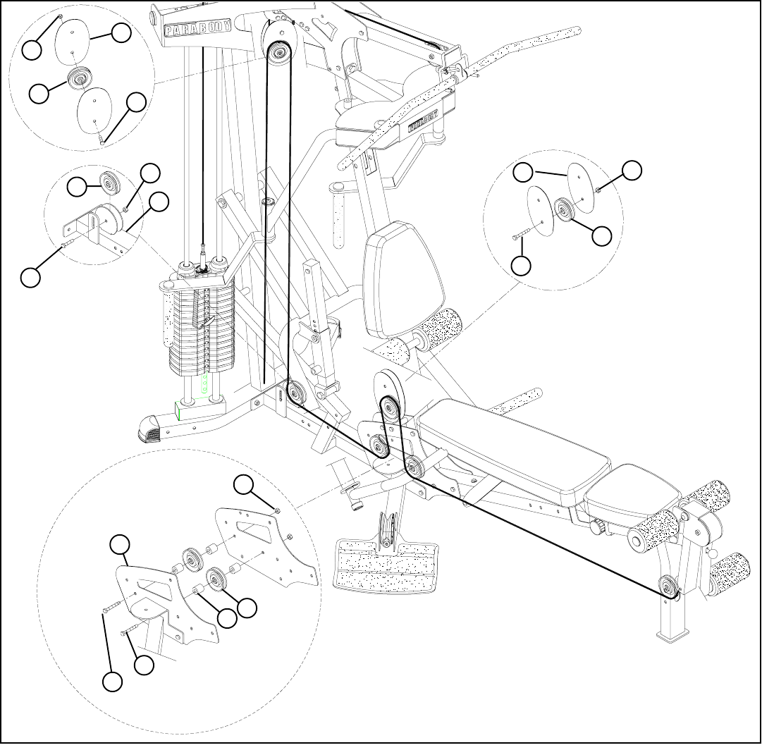
STEP 28:
FIGURE 28
• Assemble one 3-1/2” PULLEY (49) to the BASE PLATES (B) using one 3/8 X 4” BOLT (10), one 3/8 X 15/16” SPACER (30) and one 3/8”
LOCK NUT (28). See FIGURE 28(a) (Note: Loop the LOW CABLE (AW) around the PULLEY prior to assembling the PULLEY to the
BASE PLATES.)
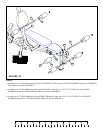
• Route the LOW CABLE (AW) around one 3-1/2” PULLEY (49) and assemble the 3-1/2” PULLEY (49) to the PULLEY PLATES (L) using
one 3/8 X 1-3/4” BOLT (17) and one 3/8” LOCK NUT (28). See FIGURE 28(b)
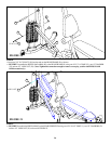
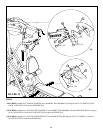
• Route the LOW CABLE (AW) around one 3-1/2” PULLEY (49) and assemble the 3-1/2” PULLEY (49) to the bracket on the BASE (A) using
one 3/8 X 1-3/4” BOLT (17) and one 3/8” LOCK NUT (28). See FIGURE 28(c)
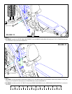
• Route the LOW CABLE (AW) around one 3-1/2” PULLEY (49) and assemble the 3-1/2” PULLEY (49) to the PULLEY PLATES (L) using
one 3/8 X 1-3/4” BOLT (17) and one 3/8” LOCK NUT (28). See FIGURE 28(d)
B
28
L
49
28
28
49
3/8 X 1-3/4”
17 3/8 X 1-3/4”
49
30
A
11 3/8 X 3-3/4”
10 3/8 X 4”
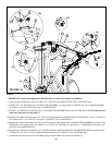
• Assemble one 3-1/2” PULLEY (49) to the BASE PLATES (B) using one 3/8 X 3-3/4” BOLT (11), one 3/8 X 15/16” SPACER (30) and one
3/8” LOCK NUT (28). See FIGURE 28(a) (Note: Loop the LOW CABLE (AW) around the PULLEY prior to assembling the PULLEY to
the BASE PLATES.)
26
(a)
(c)
(d)
(b)
28
17
L
49
17