


15
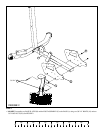
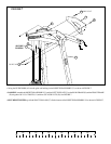
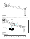
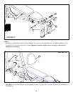
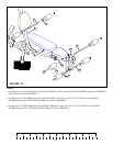
STEP 11:
FIGURE 11
• CAREFULLY slide the SEAT ADJUST (M) onto the SEAT FRAME (AF) as shown. The SEAT can be adjusted and tightened using
the PLUNGER PIN.
AF
M
0
1
2
345
6
1/2 1/2 1/2 1/2 1/2 1/2
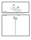
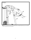
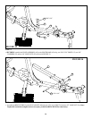
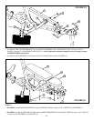
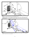
FIGURE 12
STEP 12:
• SECURELY assemble the SEAT FRAME (AF) to the BASE PLATES (B) using two 3/8 X 3-3/4” BOLTS (11) and two 3/8” LOCK NUTS
(28) as shown in FIGURE 12.
AF
B
28
3/8 X 3-3/4” 11
PLUNGER
PIN