


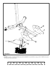
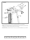
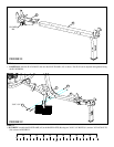
FIGURE 7
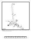
STEP 7:
11
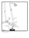
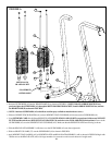
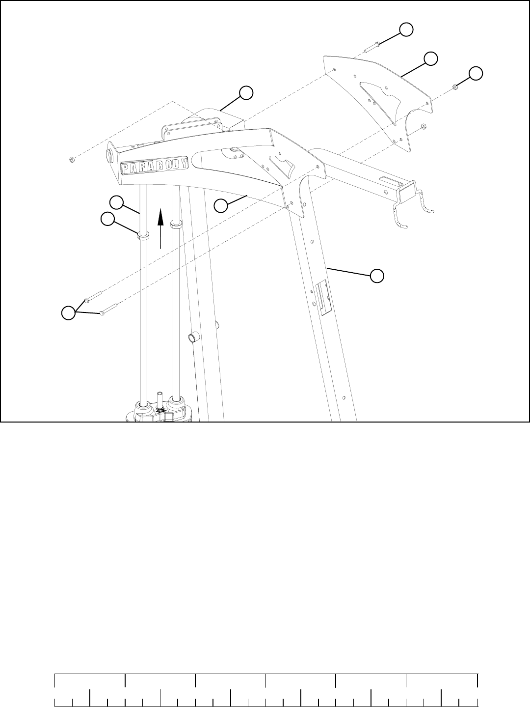
• Swing the GUIDE RODS (AI) into the guide rod bushings in the RIGHT TOP ASSEMBLY (Y) as shown in FIGURE 7.
• LOOSELY assemble the RIGHT TOP ASSEMBLY (Y) and the LEFT TOP PLATE (Y) to the REAR FRAME (D) and the FRONT FRAME
(E) using three 3/8 X 3-3/4” BOLTS (11) and three 3/8” LOCK NUTS (28). See FIGURE 7.
0
1
2
345
6
1/2 1/2 1/2 1/2 1/2 1/2
3/8 X 3-3/4” 11
28
37
AI
11 3/8 X 3-3/4”
Y
D
X
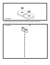
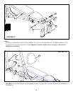
• SECURELY TIGHTEN top of both SHAFT COLLARS (37) flush to bottom of the RIGHT TOP ASSEMBLY (X)as shown in FIGURE 7.
SECURELY
TIGHTEN!
E