


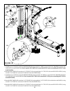
FIGURE 24
22
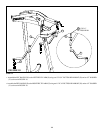
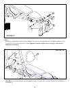
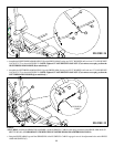
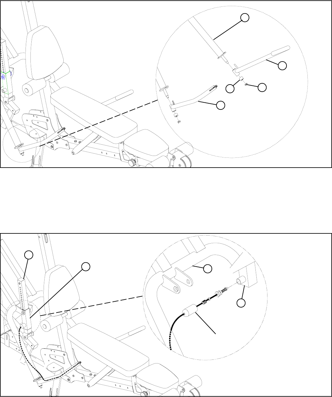
STEP 24:
R
27
I
Q
• Assemble the RIGHT PRESS ARM HANDLE (R) to the PRESS ARM (I) using one 25/32” BUMPER (AO) and one 1/2” LOW HEIGHT
LOCK NUT (27) as shown in FIGURE 24. (NOTE: Tighten 1/2” LOW HEIGHT LOCK NUT (27) to remove excess play yet allow the
RIGHT PRESS ARM HANDLE (R) to rotate freely.)
• Assemble the LEFT PRESS ARM HANDLE (Q) to the PRESS ARM (I) using one 25/32” BUMPER (AO) and one 1/2” LOW HEIGHT
LOCK NUT (27) as shown in FIGURE 24. (NOTE: Tighten 1/2” LOW HEIGHT LOCK NUT (27) to remove excess play yet allow the
LEFT PRESS ARM HANDLE (Q) to rotate freely.)
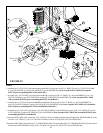
FIGURE 25
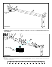
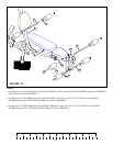
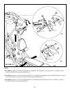
STEP 25:
PUSH-PULL
CABLE
I
AH
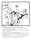
• SECURELY assemble the SPRING PIN ASSEMBLY of the PUSH/PULL CABLE to the spring pin barrel on the PRESS ARM ADJUST-
MENT TUBE (AH). (!!! IMPORTANT !!! TIGHTEN THE NUT OF THE SPRING PIN ASSEMBLY SECURELY)
• Swing the PRESS ARM (I) up until the SPRING PIN of the PUSH/PULL CABLE engages in one of the adjustment holes on the PRESS
ARM ADJUSMENT (G).
G
AH
AO