


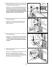
14. Tap two 1Ó Retainer Rings (32) and a 1Ó Round Cover
Cap (81) onto one end of the Press Frame Tube (34).
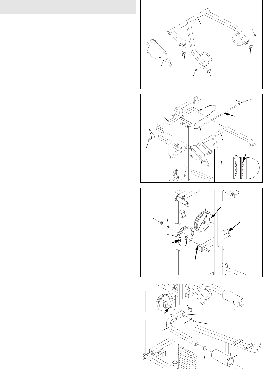
Lubricate the Press Frame Tube in its entire length.
Note: Use the Cover Cap to tap on the Retainer
Rings. Make sure the teeth on the Retainer Rings
bend towards the Cover Cap (see inset drawing).
Have one person lift up the Press Frame (8) while a
second person slides the indicated end of the Press
Frame Tube (34) through the bracket on the Top
Frame (9) and the pre-assembled Large Bushings
(44) in the Press Frame. Hold up the Press
Adjustment Frame (14) and slide the Press Frame
Tube through it and the bracket on the Top Frame.
Secure the Press Frame Tube with two 1Ó Retainer
Rings (32) and a 1Ó Round Cover Cap (81).
9
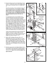
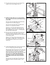
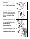
16. Press two 2Ó Square Inner Caps (28) into the open
ends of each Butterfly Arm (10). Wet the end of each
Arm with soapy water. Slide a Butterfly Foam Pad
(29) onto the indicated end of each Arm. Make sure a
Butterfly Bushing (88) has been pre-assembled on
each side of the Butterfly Arms.
Lubricate the indicated rod on the crossbar attached
to the Main Upright (1). Orient one Butterfly Arm (10)
as shown and slide it onto the rod. Secure the
Butterfly Arm with a 3/4Ó Retainer Ring (31) and a
3/4Ó Dome Cap (82). Make sure the teeth on the
Retainer Ring bend towards the Dome Cap as
shown above. Assemble the other Butterfly Arm (10)
on the opposite side of the crossbar. Follow the pro-
cedure described above, but orient the Butterfly Arm
as shown.
16
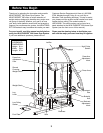
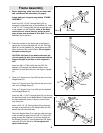
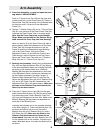
13. Press Arm AssemblyÑLocate and open the parts
bag labeled ÒARM ASSEMBLY.Ó
Press a 2Ó Square Inner Cap (28) into the open end
of each press arm on the Press Frame (8). Press a 1Ó
Round Inner Cap (58) into each of the indicated holes
on the press arms. Locate the Press Adjustment
Frame (14).
13
28
14
58
32
14
81
32
9
81
14
8
34
44
28
1
29
10
10
31
82
88
28
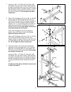
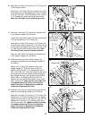
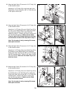
15. Butterfly Arm Assembly. Identify the Left Adjustment
Disc (26) and Right Adjustment Disc (27) by looking
at the three adjustment holes and orienting the Discs
as shown in the drawing. Make sure a Butterfly
Bushing (88) has been pre-assembled on each side
of the Adjustment Discs. Lubricate the indicated rod
on the crossbar attached to the Main Upright (1).
Slide the Right Adjustment Disc (27) onto the rod.
Secure the Adjustment Disc with a 3/4Ó Retainer Ring
(31) and a 3/4Ó Dome Cap (82). Assemble the Left
Adjustment Disc (26) in the same manner. Make sure
the teeth on the Retainer Ring bend towards the
Dome Cap as shown above.
15
82
31
26
Adjustment
Holes
Adjustment Holes
Crossbar
27
58
28
8
Arm Assembly
28
Teeth
34
81
32
88
Lubricate
Lubricate
Lubricate